Source unlevelled messages may appear on the ENA screen during this test, and the test may time out and abort. This does not necessarily indicate a problem with the operation of the test. The work-around is to add a 3 dB pad.
This topic page applies to the E5071C using the Factory Recommended or Normal Variant test plan.
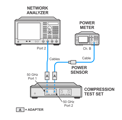
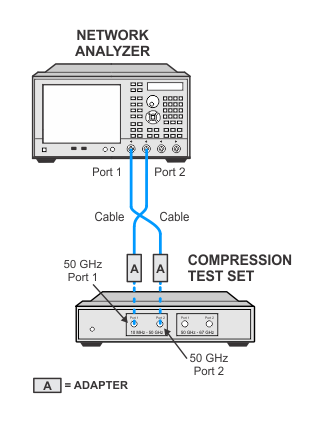
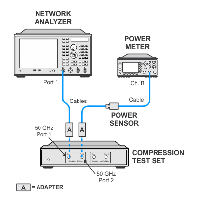
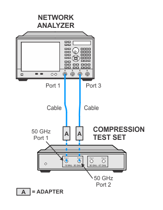
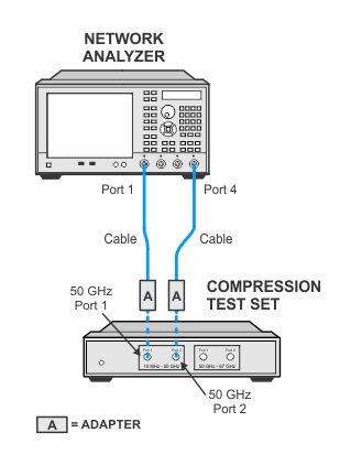
This test measures the dynamic accuracy at compression power level for the receivers with the use of the compression test set for high frequencies. The test process measures two power deltas, one at the top of the receiver input power range, and one in the middle of the input power range. The difference between the deltas represents the compression at the top of the power range. A negative test result indicates "compression" while a positive result indicates amplitude "expansion." If this test fails, there will be a note in the report stating that the dynamic accuracy result is not valid.
|
|
Source unlevelled messages may appear on the ENA screen during this test, and the test may time out and abort. This does not necessarily indicate a problem with the operation of the test. The work-around is to add a 3 dB pad. |
|
Test Equipment |
Recommended Model Number2 |
E5071C > 8.5 GHz |
E5071C ≤ 8.5 GHz |
|---|---|---|---|
|
Power meter |
N1914A |
X |
X |
|
Power sensor 1 |
E9304A Option H18 |
|
X |
|
Power sensor 3 |
E4413A |
X |
|
|
Compression test set |
U3070A-K01 |
X |
X |
|
Cable, 3.5 mm (m) to 3.5 mm (m)
|
8121-1834 |
X |
|
|
Cable, Type-N (m) to Type-N (m)
|
8120-8862 |
|
X |
|
Adapter, 3.5 mm (f) to 2.4 mm (f)
|
11901B |
X |
X |
|
Adapter, 3.5 mm (f) to 3.5 mm (f)
|
85027-60005 |
X |
|
|
Adapter, Type-N (f) to 2.4 mm (f)
|
11903B |
|
X |
|
|
|
|