
Source unlevelled messages may appear on the ENA screen during this test, and the test may time out and abort. This does not necessarily indicate a problem with the operation of the test. The work-around is to add a 3 dB pad.
This topic page applies to the E5072A using the Factory Recommended or Normal Variant test plan.
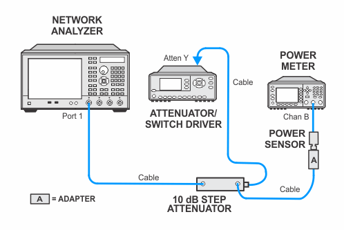
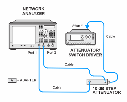
This test measures the compression at the specified maximum power level for the receivers.
This test process measures two power deltas, one at the top of the receiver input power range, and another at an expected linear part of the input power range.
A negative test result indicates compression while a positive result indicates expansion. There will be a note in the report stating:
A Fail result in this test implies that Dynamic Accuracy specification cannot be guaranteed in the Compression range of the receiver.
|
|
Source unlevelled messages may appear on the ENA screen during this test, and the test may time out and abort. This does not necessarily indicate a problem with the operation of the test. The work-around is to add a 3 dB pad. |
|
Test Equipment |
Recommended Model Number2 |
|---|---|
|
Power meter |
N1914A |
|
10 dB step attenuator |
8496G Option H52 |
|
Attenuator switch driver |
11713B |
|
Adapter, Type-N (f) to Type-N (f)
|
1250-1472 |
|
Cable, 3.5 mm (m) to 3.5 mm (m)
|
8121-1834 |
|
Cable, Type-N
|
8120-8862 |
|
|
|
Due to the complexity of the ENA family of analyzers, only a single representative model will be shown. To expand all, click the Expand All button |


 in the toolbar (webhelp only).