For Type-N Connector PNA Models
E8356A, E8357A, E8358A
E8801A, E8802A, E8803A
N3381A, N3382A, N3383A
Test Equipment
Recommended Model
Alternate Model
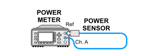
Power meter1
N1914A
E4419A/B
EPM-442A
N1912A
Power sensor
N8482A
8482A
Power sensor
(for > 3 GHz to 9 GHz models)
(not required when testing 3 GHz models)
N8481A
8481A
Power sensor cable
(Qty 2)
(1 required when testing 3 GHz models)
11730A
none
1. When testing PNAs that have a frequency range up to 3 GHz, the E4418A/B power meter can be used; therefore the E4412A power sensor and power sensor cable will not be required.
For 3.5 mm Connector PNA Models
E8362A, E8362B, E8362C
Test Equipment
Recommended Model
Alternate Model
Power meter
N1914A
E4419A/B
EPM-442A
N1912A
Power sensor
N8482A
8482A
Power sensor
N8485A
E9300A H25
8485A
Power sensor cable
(Qty 2)
11730A
equivalent
Adapter 3.5 mm (f) to 3.5 mm (f)
83059B
1250-1749
Adapter 3.5 mm (f) to Type-N (f)
1250-1745
equivalent
Adapter 3.5 mm (f) to Type-N (m)
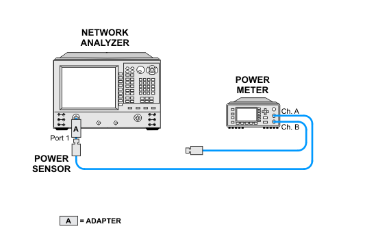
(for power sensor calibration)
1250-1744
08485-60005
For 2.4 mm Connector PNA Models
E8363A, E8363B, E8363C
E8364A, E8364B, E8364C
Test Equipment
Recommended Model
Alternate Model
Power meter
N1914A
E4419A/B
EPM-442A
N1912A
Power sensor
N8482A
8482A
Power sensor
N8487A
8487A
Power sensor cable
(Qty 2)
11730A
equivalent
Adapter 2.4 mm (f) to 2.4 mm (f)
11900B
85058-60114
(1.85 version from cal kit)
Adapter 2.4 mm (f) to Type-N (f)
11903B
equivalent
Adapter 2.4 mm (f) to Type-N (m)
(for power sensor calibration)
11903D
08487-60001
For 1.85 mm Connector PNA Models
E8361A, E8361C
Test Equipment
Recommended Model
Alternate Model
Power meter
N1914A
E4419A/B
EPM-442A
N1912A
Power sensor
N8482A
8482A
Power sensor
N8487A
8487A
Power sensor
N8488A
V8486A with the V281A waveguide adapter1
(includes Option H67)2
Power sensor cable
(Qty 2)
11730A
equivalent
Adapter 2.4 mm (f) to 2.4 mm (f)
11900B
85058-60114
(1.85 version from cal kit)
Adapter 2.4 mm (f) to Type-N (f)
11903B
equivalent
Adapter 2.4 mm (f) to Type-N (m)
(for power sensor calibration)
11903D
08487-60001
- Combination of the V8486A power sensor and V281A adapter must be calibrated as a single unit—do not separate. For more information, click here.

- Option H67 is an ANSI Z540-1 calibration for the V8486A power sensor with a V281A connector adapter (connected together).