30 dB Attenuator Insertion Loss
This test applies to the following models:
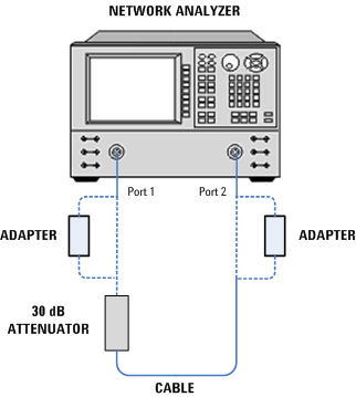
This test which measures the insertion loss of the 30 dB fixed attenuator. The purpose of this test is to
measure the insertion loss of the 30 dB fixed attenuator at 50 MHz and store the
measured attenuation value to the power sensor’s EEPROM.
|

|
If the adapters
and cables are used to connect the 30 dB fixed attenuator to the PORT 1 and
2 of the Network Analyzer, ensure that the adapters and cables are not
disconnected at any time since the last Two Port Network Analyzer Calibration. If
the VSWR test is performed next, ensure that the adapter remains connected
to the PORT 1 for the VSWR test.
|
Required Test Equipment
| Instrument |
Recommended product |
Alternative product |
N8481B |
N8482B |
N8482B
Opt Z2092B-208 |
| PNA |
N5247B |
N5247A/AS
N5245B
N5245A/AS
E8361C
E8361A
E8364B
E8364C
N5230A[1]
N5230C[1]
|
X |
- |
X |
| ENA |
E5071C[2] |
- |
- |
X |
- |
| Power Meter |
N1914B |
N1914A
N1912A
E4419B |
X |
X |
X |
| Type-N cable |
11500C |
11500B (Only for UUT N8482B) |
X |
X |
X |
| 2.4 mm (f) to Type-N (f) (2 required) |
11903B |
- |
X |
- |
X |
[1] Supported N5230A and N5230C Options: This calibration application
supports any option that covers the entire frequency range of the UUT.
[2] Supported E5071C Options: This calibration application
supports any option that covers the entire frequency range of the UUT.
Store the New Insertion Loss to the UUT EEPROM
The storing is also applicable for the N848xB power sensors with option CFT.
If the result is a fail, the measured insertion loss will not be written to the EEPROM of the UUT.
The storing procedure differs according to the type of power meter used.
- If an E4419B power meter is used, additional steps are required as shown below:
Disconnect the UUT from Channel A of the power meter, and ensure there
is no power sensor connected to Channel B of the power meter.
Connect the UUT to Channel A of the power meter.
The calibration factors will be written to the EEPROM of the UUT.
Disconnect the UUT from Channel A of the power meter and ensure there is
no power sensor connected to Channel B of the power meter.
Connect the UUT to Channel A of the power meter.
The storing of the calibration factors will be completed. You may choose
to run the Calibration Factor Read and Write utility to view the calibration
factors stored in the EEPROM of the UUT.
|
|
Steps i and ii
are required to disable the temperature update in the EPM power meter which
will disturb the write operation. Steps iv and v are required to enable the
temperature update back in the EPM power meter.
|
-
If an N1912A or N1914A power meter is used, the storing process will be
executed automatically with the UUT always connected to Channel A of the power meter. The additional steps required to disable and enable the temperature
update in the EPM power meter are not applicable for the P-Series power meter.
30 dB Attenuator Insertion Loss Test Setup