VSWR

This test measures the Voltage Standing Wave Ratio (VSWR) of the Keysight power sensor. A network analyzer accompanied with a calibration kit or electronic calibration modules is used to perform this test.

Required Test Equipment

Instrument Recommended product Alternative product U2000A,U2000B, U2000H U2001A,U2001B, U2001H U2002A,U2002H
U2004A
Network analyzers
PNA1

N5247B

N5245A/AS

N5245B

N5247A/AS

E8361C
E8361A
E8364B
E8364C

N5230A2
N5230C2

X X X  
ENA E5071C3 -       X
Calibration Kits/Electronic Calibration Modules
50 Ω Calibration Kit 85054B
N4690B Opt M0F or 85032F (for U2001A, U2001B, and U2001H only)
X X    
50 Ω Calibration Kit 85032F -       X
50 Ω Calibration Kit 85052B N4691B Opt M0F
or
N4691BH33 Opt M0F
    X  
Meters
Power Meter4 N1914A N1912A
E4419B
      X
Power Sensor5 N8481A
N8481B or N8481H or  8481A or
8481B or 8481H
X X    
Power Sensor5 N8485A
8485A     X  
Power Sensor5 E9304A -
      X
Adapters6
2.4 mm (f) to 3.5 mm (f) 11901B
-     X  
2.4 mm (f) to Type-N (f) 11903B
- X X    

Table Footnotes:

  1. The following minimum PNA firmware revisions or above are required to include phase wrapping fix:

    • E8361A, E8364B, N5230A: A.07.50.57
    • E8361C, E8364C, N5230C: A.09.00.02


  2. Supported N5230A and N5230C options: This calibration application software supports any option that covers the entire frequency range of the UUT. Supported options: 420, 425, 520, and 525.

  3. Supported E5071C options: This calibration application software supports any option that covers the entire frequency range of the UUT.

  4. The following notes apply to power meters:

    • N1914A

      • N1914A power meters with serial number prefix prior to MY53040007 require Service Note N1914A-07 which fixes a power supply ground loop. The ground loop injects noise into the measurement circuits which can cause unstable measurements at low (–30 dBm) power levels.
      • Requires minimum firmware version A.01.15 or above to fix a power linearity accuracy issue.


    • N1912A requires minimum firmware version A.05.10 or above to fix a power linearity accuracy issue.


  5. Supported power sensor options:

    • N8480 Series: STD or CFT
    • N8485A: STD or CFT and/or 033
    • 8485A: Standard Option or 033

    Refer to Required Calibration Data section in Test Equipment page for the calibration options that meet the TME requirement on the test equipment's calibration data.

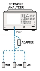
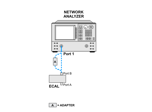
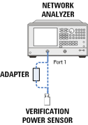
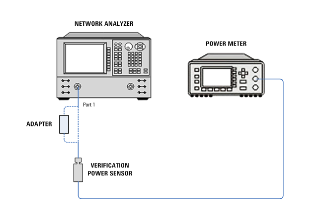
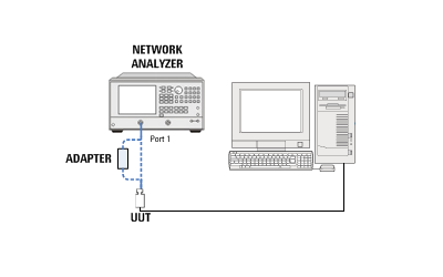
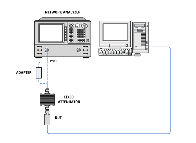
  6. Use other type of adapter that suits the network analyzer’s connector type where necessary.

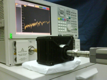
    When connecting the power sensor model U2000B or U2001B to the network analyzer's test port, please ensure the fixed attenuator is supported by an object or fixture to prevent bending on the adapter or connector. See the picture below for an example of the connection.

E-Cal Usage

An E-Cal may be used for the network analyzer calibration instead of a mechanical calibration kit. When using the E-Cal, please connect it to the network analyzer using a USB cable. Before using the E-Cal, ensure that the ready light has turned green on the unit. When mapping the E-Cal in TME, the serial number should be a 5 digit number with no letters. If there is no 5 digit serial number printed on your unit, then follow these instructions using your network analyzer to locate your serial number:

  1. Connect the E-Cal to the network analyzer using a USB cable.
  2. Press the Cal button.
  3. Press the Cal Wizard key.
  4. Choose Use Electronic Calibration.
  5. On this screen you should see the model number of your E-Cal followed by a five digit serial number.

Network Analyzer Calibration

Using Calibration Kit:


Using Electronic Calibration Modules:

Test Setup for Network Analyzer Calibration Verification

Using N8480 Series or 8480 Series power sensor:


Using E9304A power sensor:

VSWR Performance Verification Test Setup

For all UUT, except U2000B and U2001B:

For U2000B and U2001B: