The VSWR test should be performed prior to running this test.
|
|
The VSWR test should be performed prior to running this test. |
The purpose of this test is to characterize the Calibration Factor of the power sensor module at each frequency parameter. The generated calibration data will be saved to an XML format file in:
Windows 10:
C:ProgramData\Agilent Technologies\Test Management Environment\N5532X\CalFactorXMLData
This file can be copied to a disk to transfer the cal data to the N5530S, N5531S, or N5531X Measuring Receiver Systems.
The calibration factor uncertainty is stated as an absolute uncertainty. Stating calibration factor uncertainty as an absolute uncertainty allows for a consistent reporting format in TME.
Calibration factor uncertainty can be stated as a relative or an absolute number. Traditionally, calibration factor uncertainty has been stated as a relative number. Measurement uncertainty calculations require that this parameter be a relative term. It is critical that this distinction between absolute and relative uncertainties be understood when performing measurement uncertainty calculations. The power sensor module relative calibration factor uncertainty can be derived from the absolute calibration factor uncertainty by the following equation.
Relative calibration factor uncertainty = 100% × (Absolute calibration factor uncertainty) / (Calibration factor)
In general, the difference between the relative and absolute uncertainty is less than 10%. This small difference is because calibration factor values tend to be greater than 90% on a typical power sensor.
|
Test Equipment |
Recommended Model Number |
Option 504 |
Option 518 |
Option 526 |
Option 550 |
|
Signal Generator |
E8257D |
X |
X |
X |
X |
|
Function Generator |
33622A |
X |
|
|
|
|
Power Meter |
N1914B |
X |
X |
X |
X |
|
Power Sensor, Type-N, 18 GHz1 |
N8481A |
|
X |
|
|
|
Power Sensor, Type-N, 6 GHz1 |
N8482A |
X |
|
|
|
|
Power Sensor, 3.5 mm, 26.5 GHz1 |
N8485A |
|
|
X |
|
|
Power Sensor, 2.4 mm, 50 GHz1 |
N8487A |
|
|
|
X |
|
Power Splitter, Type-N2 |
11667A Option H86 |
X |
X |
|
|
|
Power Splitter, 3.5 mm2 |
11667B Option H86 |
|
|
X |
|
|
Power Splitter, 2.4 mm2 |
11667C Option H86 |
|
|
|
X |
|
50Ω Termination, 3.5 mm |
902D |
X |
X |
X |
|
|
50Ω Termination, 2.4 mm |
901D |
|
|
|
X |
|
Type-N cable |
11500C |
X |
|
|
|
|
Adapter, 2.4 mm (f) to Type-N (m) |
11903D |
X |
X |
|
|
|
Adapter, BNC (m) to Type-N (f) |
1250-1477 |
X |
|
|
|
|
Adapter, 2.4 mm (f) to 3.5 mm (m) |
11901D |
|
|
X |
|
|
Adapter, 3.5 mm (f) to Type-N (m)3 |
08485-60005 |
|
|
X |
|
|
Adapter, 2.4 mm (f) to Type-N (m)3 |
08487-60001 |
|
|
|
X |
|
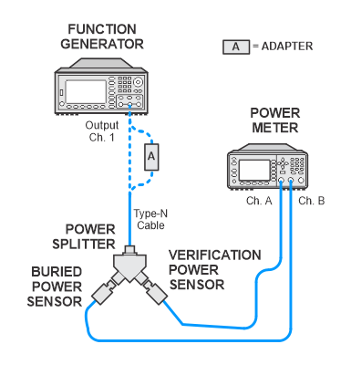
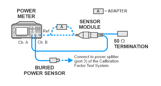
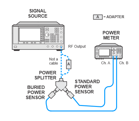
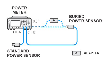
The test setup diagrams are divided by option.
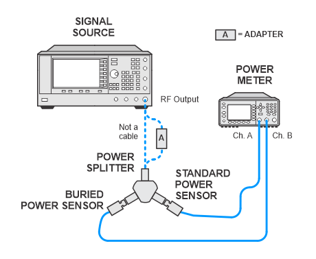
Calibrate Standard Power Sensor (Channel A)
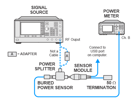
Calibrate Buried Power Sensor (Channel B)
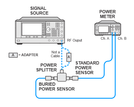
Calibration Factor Test System Characterization

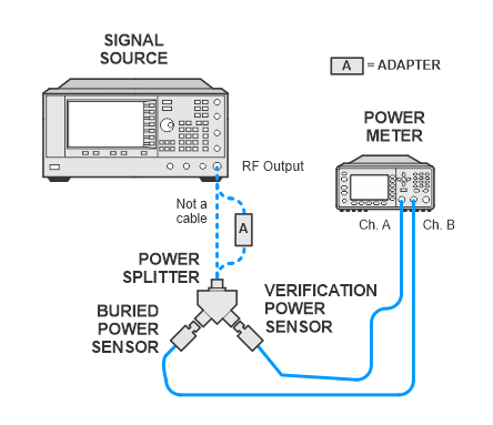
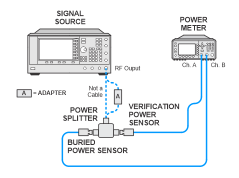
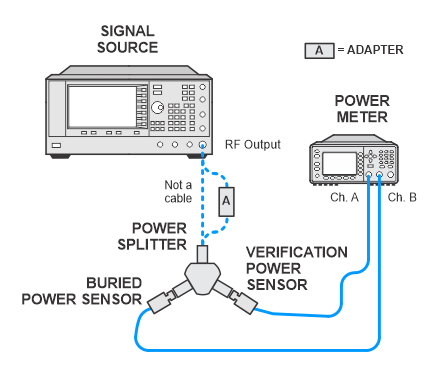
Calibrate Verification Power Sensor (Channel A)
Calibration Factor Test System Verification
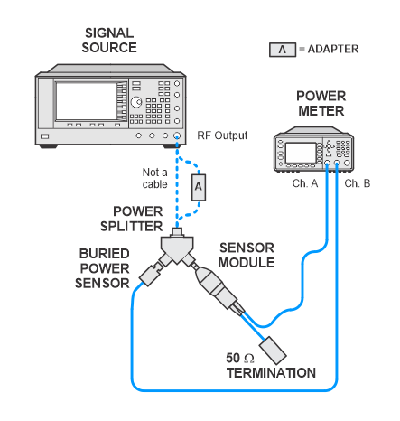
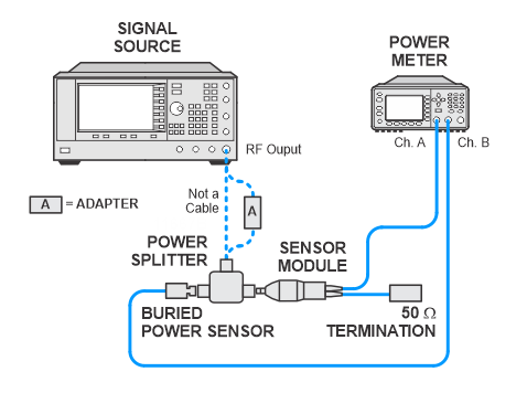
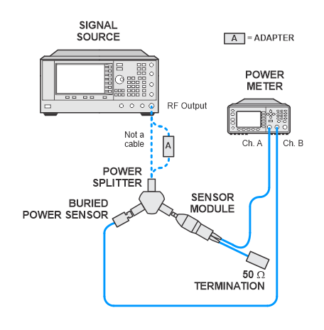
Calibrate UUT Power Sensor (Channel A)
N5532A/B
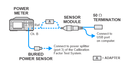
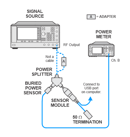
Calibrate UUT Power Sensor
U5532C
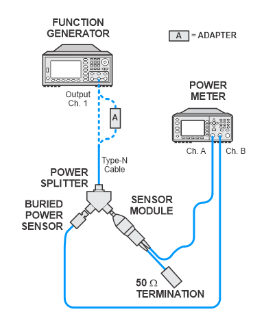
Calibration Factor Test Setup
N5532A/B
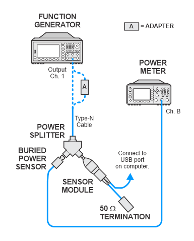
Calibration Factor Test Setup
U5532C

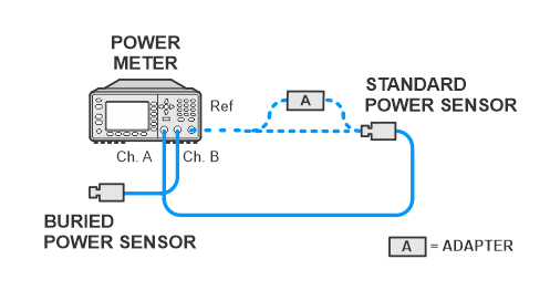
Calibrate Standard Power Sensor (Channel A)
Calibrate Buried Power Sensor (Channel B)
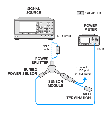
Calibration Factor Test System Characterization
Calibrate Verification Power Sensor (Channel A)
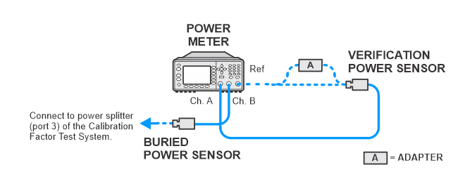
Calibration Factor Test System Verification
Calibrate UUT Power Sensor (Channel A)
N5532A/B
Calibrate UUT Power Sensor
U5532C
Calibration Factor Test Setup
N5532A/B
Calibration Factor Test Setup
U5532C
Calibrate Standard Power Sensor (Channel A)
Calibrate Buried Power Sensor (Channel B)
Calibration Factor Test System Characterization
Calibrate Verification Power Sensor (Channel A)
Calibration Factor Test System Verification
Calibrate UUT Power Sensor (Channel A)
N5532A/B
Calibrate UUT Power Sensor
U5532C
Calibration Factor Test Setup
N5532A/B
Calibration Factor Test Setup
U5532C