M9389A
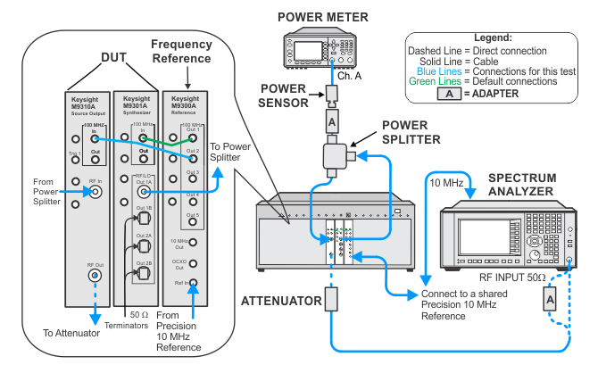
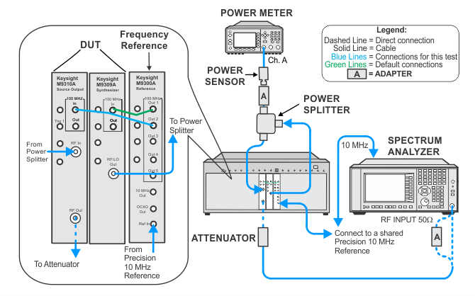
The output section of the DUT includes four electronic attenuators. The purpose of this adjustment is to measure the actual attenuation provided by the combination of these four attenuators at each step in the predefined sequence of settings.
|
Test Equipment |
Recommended Models1 |
|
Spectrum analyzer |
N9030A Option 5xx2 |
|
Power meter |
N1914A |
|
Power sensor |
E9304A H20 |
|
Power splitter, 3.5 mm (f) |
11667B |
|
Attenuator, 6 dB Fixed |
8493C Opt. 006 |
|
Precision 10 MHz reference |
Microsemi 5071A |
|
50 W terminator
|
909D |
|
Adapter, Type-N (f) to 3.5 mm (m) |
1250-1750 |
|
Adapter, 3.5 mm (f) to 2.4 mm (f) |
11901B |
|
Cable, 3.5 mm (m) to 3.5 mm (m)
|
11500E |
|
Cable, BNC (m) to SMB (f) |
8121-2063 |
|
Cable, 3.5 mm (m) to 3.5 mm (m)
|
8121-1221 |
|
100 MHz reference |
M9300A |
|
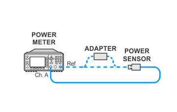
Setup for Power Meter Calibration

Setup for ALC and Out Atten Adjustment (M9380A, M9381A)

Setup for ALC and Out Atten Adjustment (M9389A)

