M9381A
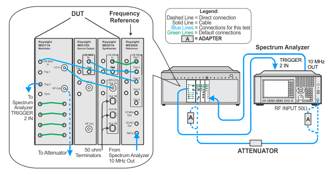
This process corrects the IQ modulation gain and phase imbalance. The IQ Map adjustment measures modulator gain imbalance, quadrature phase imbalance, and DC offset at several RF frequencies in each frequency band defined by the RF low-pass filter selected. It calculates a matrix based on the gain and phase imbalance of I and Q and creates a correction matrix to fix these imbalances.
|
Test Equipment |
Recommended Models1 |
|
Spectrum analyzer |
N9030A Option 5xx2 |
|
Attenuator, 6 dB Fixed |
8493C Opt. 006 |
|
50 W terminator
|
909D |
|
Adapter, 3.5 mm (f) to 2.4 mm (f) |
11901B |
|
Cable, 3.5 mm (m) to 3.5 mm (m)3
|
8121-1221 |
|
Cable, BNC (m) to SMB (f)3
|
8121-2063 |
|
100 MHz reference |
M9300A |
|
Setup for IQ Map Adjustment

