M9381A
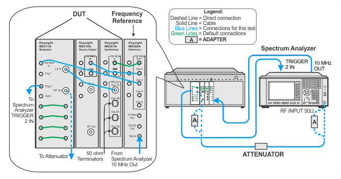
This alignment measures the relative attenuation provided by the output attenuator. The adjustment procedure measures the DUT's output power at each attenuator setting relative to the output power at the nominally 0 dB attenuation setting. The change in measured power determines the amount of attenuation supplied by each attenuator setting at the measurement frequency.
|
Test Equipment |
Recommended Models1 |
|
Spectrum analyzer |
N9030A Option 5xx2 |
|
Attenuator, 6 dB Fixed |
8493C Opt. 006 |
|
50 W terminator
|
909D |
|
Adapter, 3.5 mm (f) to 2.4 mm (f) |
11901B |
|
Cable, 3.5 mm (m) to 3.5 mm (m)3
|
8121-1221 |
|
Cable, BNC (m) to SMB (f)3
|
8121-2063 |
|
100 MHz reference |
M9300A |
|
Setup for Output Attenuation Adjustment

