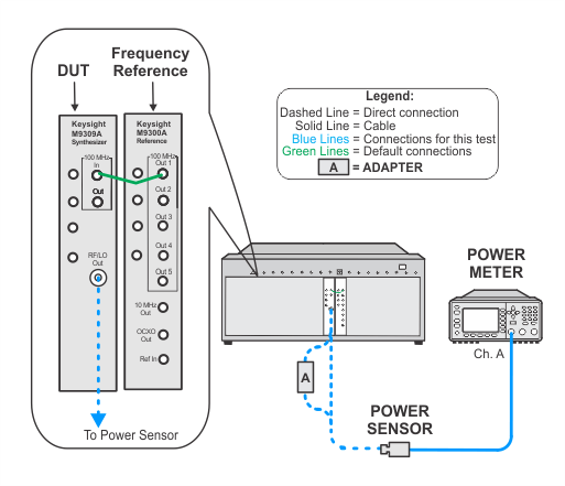
M9389A
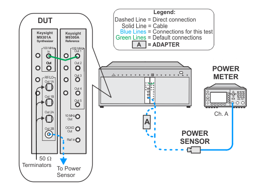
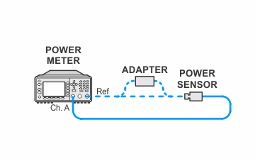
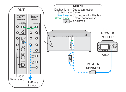
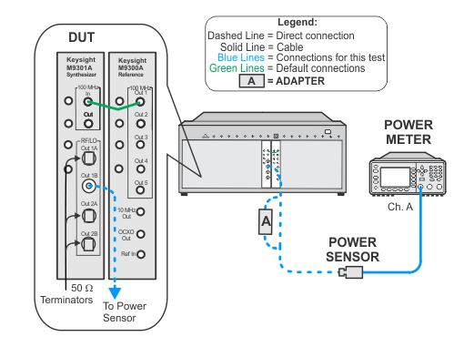
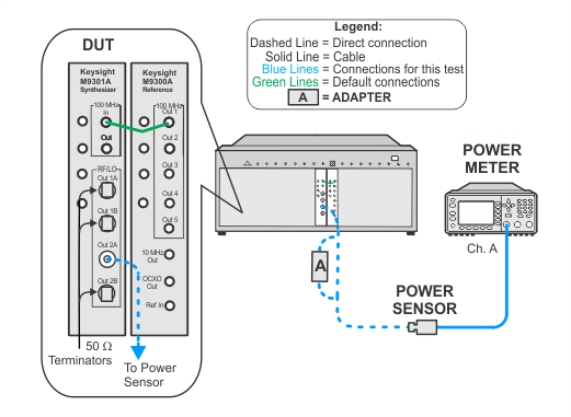
There are four power adjustments, one for each RF output port (1A/B and 2A/B) on the M9380A and M9381A, and one on the M9389A RF/LO output port. In this process, a separate measurement is made at each RF output using a power meter, and based on the result a computer algorithm calculates the value to adjust the output step attenuator.
|
Test Equipment |
Recommended Models1 |
|
Power meter |
N1914A |
|
Power sensor |
E9304A H20 |
|
50 W terminator
|
909D |
|
Adapter, Type-N (f) to 3.5 mm (m) |
1250-1750 |
|
100 MHz reference |
M9300A |
|
Setup for Power Meter Calibration

RF/LO Out 1A
RF/LO Out 1B
RF/LO Out 2A
RF/LO Out 2B
