M9381A
This adjustment procedure measures the output power of the IQ modulator at several frequencies in each of eight RF filter paths. Once all frequencies in the filter path have been measured, the phase change across the band is calculated resulting in both magnitude and phase information. This information is used to adjust the filters.
|
Test Equipment |
Recommended Models1 |
|
Power meter |
N1914A |
|
Power sensor |
E9304A H20 |
|
50 W terminator
|
909D |
|
Adapter, Type-N (f) to 3.5 mm (m) |
1250-1750 |
|
100 MHz reference |
M9300A |
|
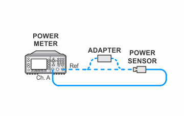
Setup for Power Meter Calibration

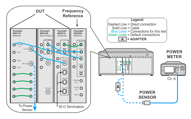
Setup for RF Response Adjustment

