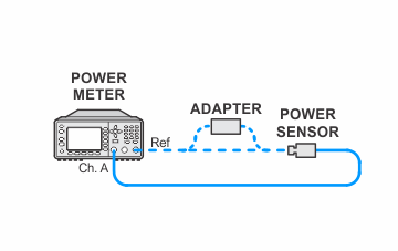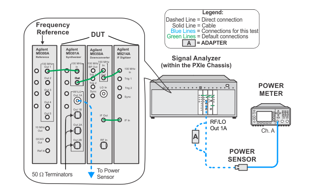
For procedures that apply to multiple ports, illustrations will show the setup on only one test port.
There are four power adjustments, one for each RF output port (1A/B and 2A/B) on the M9301A Synthesizer. In this process, a separate measurement is made at each RF output using a power meter and, based on the result, a computer algorithm calculates the value to adjust the output step attenuator.
|
Test Equipment |
Recommended Models1 |
|
Power meter |
N1914A2 |
|
Power sensor |
E9304A Opt. H20 |
|
Adapter, Type-N (f) to 3.5 mm (m) |
1250-1750 |
|
Frequency reference module |
M9300A |
|
|
|
|
For procedures that apply to multiple ports, illustrations will show the setup on only one test port. |
Setup for Power Meter Calibration

Setup for Synthesizer Adjustment

