Option F1A covers 1.1 to 1.8 GHz, 2.3 to 2.6 GHz, and 4.8 to 6 GHz.
Absolute Amplitude Accuracy is described as the amplitude accuracy versus frequency. The specification excludes IF Bandwidth Switching Uncertainty, Attenuator Accuracy, IF Flatness, Amplitude Linearity, and Conversion Mode dependencies. These other parameters will be tested separately.
|
|
Option F1A covers 1.1 to 1.8 GHz, 2.3 to 2.6 GHz, and 4.8 to 6 GHz. |
This test will measure the amplitude accuracy versus frequency. The PXIe signal analyzer has three conversion types:
Image Protect (a.k.a Double Conversion) — defined as 1 MHz to 6 GHz
Single Low — defined as 1.1 GHz to 6 GHz
Single High — defined as 400 MHz to 6 GHz
The procedure will also test three different RF Paths: Highpower, Preamp, and Standard Path. The test will be made on the B04 (40 MHz) IF Path. If the PXIe signal analyzer has either Option B10 (100 MHz IF Path) or B16 (160 MHz IF Path), the test will be repeated for that path. Potentially there will be eighteen different sets of data.
|
Test Equipment1 |
Recommended Models2 |
|
Signal generator |
M9381A Opt 1EA |
|
Power meter |
N1914A3 |
|
Power sensor |
E9304A-H20 |
|
Power splitter |
11667B |
|
Adapter, 3.5 mm (m) to 3.5 mm (m)4 |
83059A |
|
Frequency reference module |
M9300A |
|
|
|
|
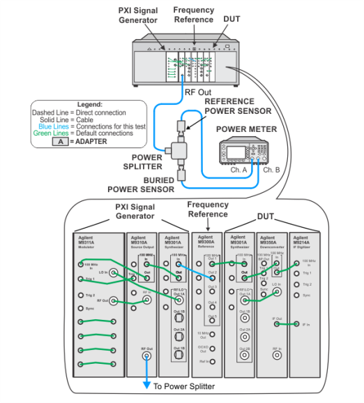
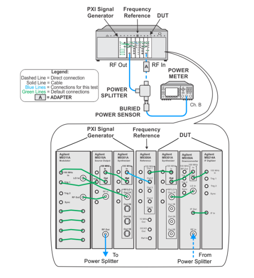
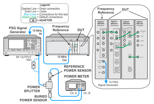
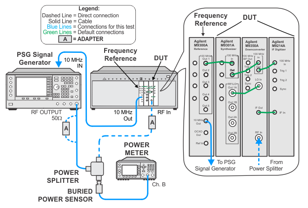
The illustrations below show the recommended M9381A PXIe signal generator. If your setup is using the alternative M9380A PXIe signal generator, refer to the M9380A Startup Guide for the default cable interconnections. |
To view the image, choose from the links below depending on your setup.

 Splitter characterization using a PXIe signal generator as the source