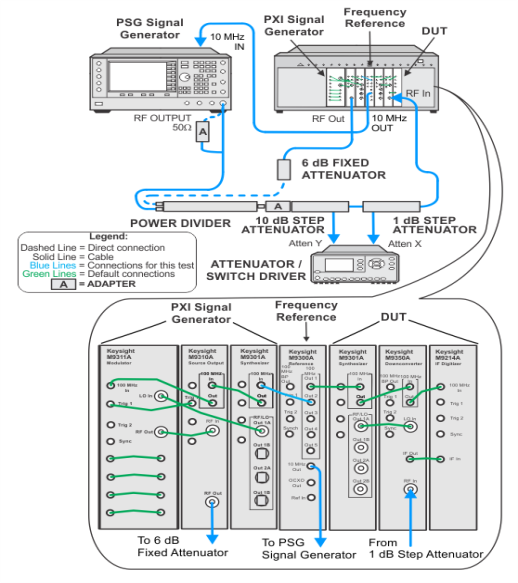
The illustrations below show the recommended M9381A PXIe signal generator. If your setup is using the alternative M9380A PXIe signal generator, refer to the M9380A Startup Guide for the default cable interconnections.
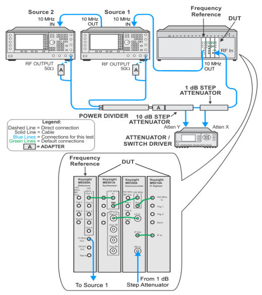
This test measures the amplitude linearity of the M9391A. Amplitude linearity is the amplitude accuracy over a range of input signals relative to an expected input level of +5 dBm. The test technique uses the two-source frequency offset method. The two source technique is accurate over small amplitude ranges, so step attenuators are used to step the amplitude over a wider range. The actual attenuator step loss is not critical as the measurement is re-referenced for each attenuator step. The linearity sections are then “stitched” together for all attenuator steps.
|
Test Equipment1 |
Recommended Models2 |
|
Signal generator3 |
M9381A Opt 1EA |
|
Power divider |
87302C |
|
Fixed attenuator, 6 dB |
8493C Opt 006 |
|
Step attenuator, 10 dB |
8496G Opt 001 |
|
Step attenuator, 1 dB |
8494G |
|
Attenuator driver |
11713B |
|
Frequency reference module |
M9300A |
|
|
|
|
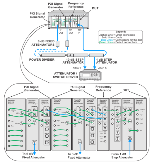
The illustrations below show the recommended M9381A PXIe signal generator. If your setup is using the alternative M9380A PXIe signal generator, refer to the M9380A Startup Guide for the default cable interconnections. |

 Test setup using two PXIe signal generators for both sources