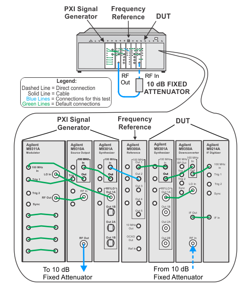
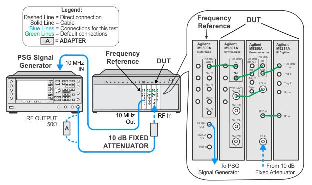
The illustrations below show the recommended M9381A PXIe signal generator. If your setup is using the alternative M9380A PXIe signal generator, refer to the M9380A Startup Guide for the default cable interconnections.
In this test a source is connected to the PXIe signal analyzer. The (UUT) attenuators are stepped by changing the “Expected Input Level” setting. The error is referenced to a –10 dBm Expected Input Level. The UUT display is used to measure the difference between the change in the internal attenuator.
The High Power Path is switched in when the Expected Input Level setting changes from +4 dBm to +5 dBm. The Crossing +5 dBm specification is essentially a range change.
The external source power is not changed during the test. The source amplitude is not critical since this is a relative measurement. Also, since the source amplitude is not changed, there are no errors associated with the source.
A fixed attenuator is placed between the UUT and the source in order to “buffer” the source mismatch from the UUT. The fixed attenuator creates a controlled match for the UUT as its internal attenuation is changing.
|
Test Equipment1 |
Recommended Models2 |
|
Signal generator |
M9381A Opt 1EA |
|
Fixed attenuator, 10 dB |
8793C Opt 010 |
|
Frequency reference module |
M9300A |
|
|
|
|
The illustrations below show the recommended M9381A PXIe signal generator. If your setup is using the alternative M9380A PXIe signal generator, refer to the M9380A Startup Guide for the default cable interconnections. |