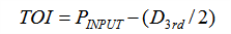
This test measures the Third-Order Intermodulation distortion produced by two discrete signals and computes the Third Order Intercept (TOI) point. The intercept point is calculated and compared to the specification. The PXIe signal analyzer is specified with the conversion path set to Auto, and 40 MHz IF Filter path. The TOI is the theoretical power level where two input signals and their third-order distortion products reach the same power level. It’s impractical to measure the intercept directly because the signal analyzer would be in severe compression. The intercept is calculated from low level measurements from the following equation:
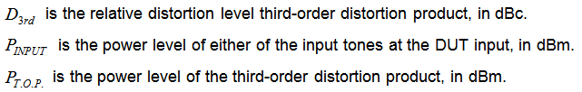
Where:
Where: 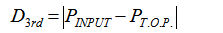
For this test, two signals separated by 100 kHz are combined in a directional bridge (for isolation) and injected into the analyzer input. The PXIe signal analyzer measures the amplitude of the lower and upper third-order distortion products. Worst-case TOI is computed by using the larger of these two distortion products.
|
Test Equipment1 |
Recommended Models2 |
|
Signal generator3 |
M9381A Opt 1EA |
|
Power meter |
N1914A4 |
|
Power sensor |
E9304A Opt H20 |
|
Power splitter |
11667B |
|
Directional bridge |
86205A |
|
50 MHz Low Pass Filter |
RLC L3230 |
|
1.0 GHz Low Pass Filter |
RLC F-30-1000-RF |
|
2.0 GHz Low Pass Filter |
RLC F-30-2000-RF |
|
3.0 GHz Low Pass Filter |
RLC F-30-3000-RF |
|
6.0 GHz Low Pass Filter |
RLC F-30-6000-RF |
|
Adapter, 3.5 mm (m) to 3.5 mm (m)5 |
83059A |
|
Frequency reference module |
M9300A |
|
|
|
|
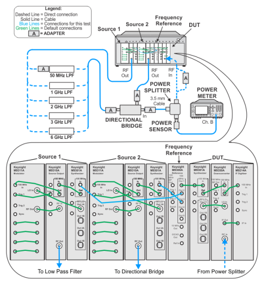
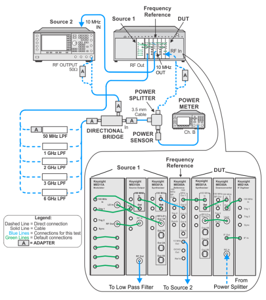
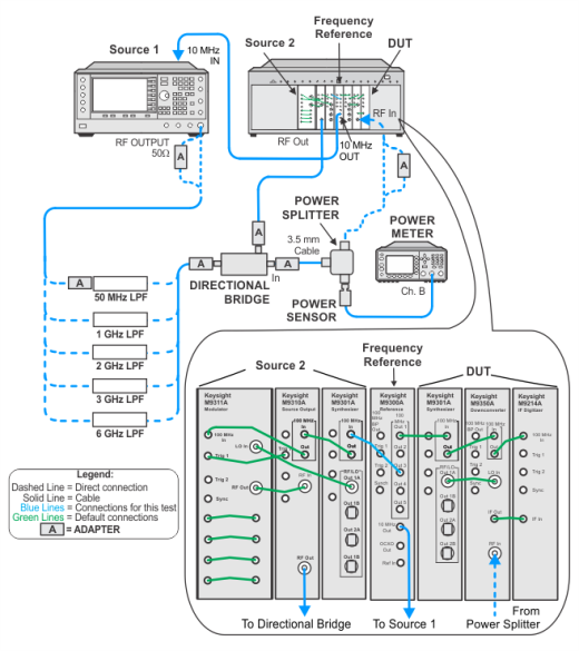
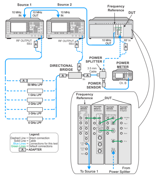
The illustrations below show the recommended M9381A PXIe signal generator. If your setup is using the alternative M9380A PXIe signal generator, refer to the M9380A Startup Guide for the default cable interconnections. |
To view the image, choose from the links below depending on your setup.


 Two PXIe signal generators for both sources