Dynamic Accuracy Performance Test
Dynamic Accuracy, as defined here, is a measure of a receiver's relative power linearity. It is the measurement accuracy of a receiver as a function of power. At a CW frequency, a signal at a known power level is delivered to the receiver which establishes a power reference value. The signal, at a new power level dB from the reference, is then delivered to the receiver.
As a result, the receiver reading will change by  dB. The difference between the delta power delivered and the delta power read by the receiver,
  dBm, will be the dynamic accuracy error. This process is repeated over the desired measurement range of the receiver. A mathematical expression for this specification (in dB) is:

When measuring dynamic accuracy, it is critical to know the difference between two power levels. It is desirable to determine how accurately the receiver measures the change in input power relative to a reference, not the absolute power measured by the receiver.
Before the test begins, a reference power must be selected. All subsequent measurements will use the reference power for computing the dynamic accuracy error. The reference power is normally selected somewhere well above the noise floor and safely below source and receiver compression.
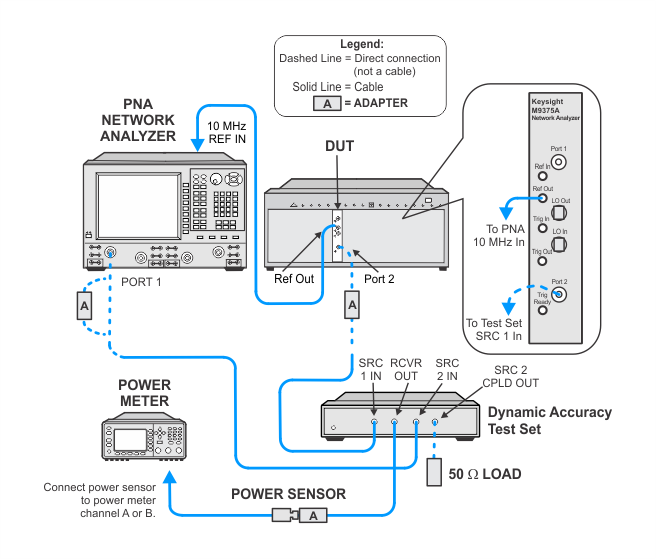
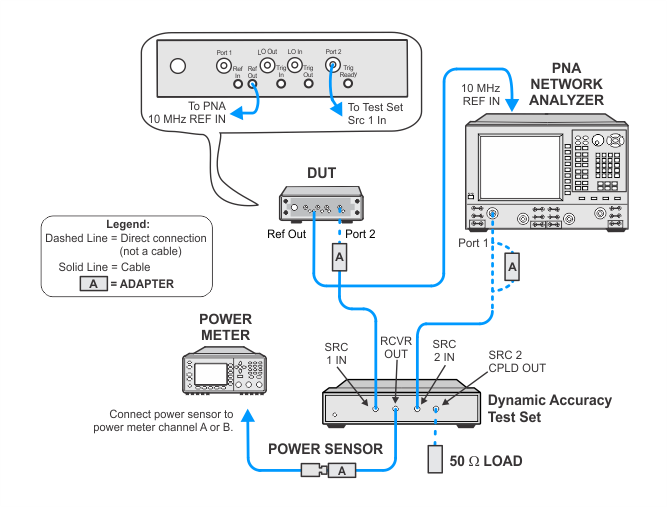
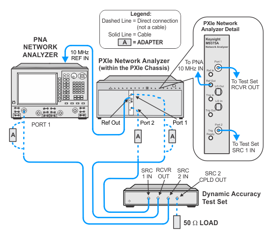
Two sources are used to provide the source power to the receiver through a special combining network. The source power at the receiver is adjusted to deliver a target power with one source. The power at the receiver is then measured with the target power applied. That source is then turned off and the other source is turned on and adjusted, using the receiver as the measurement device, to achieve the same power at the receiver.
The variation in power is achieved by placing the two sources at a specific offset frequency from one another at a specific CW frequency which, when combined, will provide a calculable variation in power to the receiver at the specified CW frequency. A declared power range of this measurement is taken. An attenuator is also used between the combining network and the receiver to further extend the measurement range.
The dynamic accuracy error is plotted on the y-axis (dB) and the incident power to the receiver is plotted on the x-axis (dBm).
Click here for troubleshooting help.
Required Test Equipment
|
Test Equipment
|
Recommended Models1
|
|
PNA network analyzer
|
N5245B
|
|
Power meter
|
N1914A
|
|
Power sensor
|
N8485A
|
|
Dynamic accuracy test set2
|
U3020BD01
|
|
50 Ω termination
|
909D Option 301
|
|
Cable, RF 3.5 mm (m) to 3.5 mm (f)
(3 required)
|
8121-2111
|
|
Adapter, 3.5 mm (m) to 3.5 mm (m)
|
83059A
|
- Refer to the main required equipment table for a list of alternate models.
-
If needed, the GPIB address on the test set can be modified by following these steps ( click here): click here):
- Connect the new test set to the LAN.
- Open Keysight IO from the PC.
- Select Add Instrument from the menu.
- In the Add LAN Instrument window, locate the new test set on the LAN.
- Select the web page for the new test set and select the View & Modify Configuration tab at the left.
- Select Modify Configuration.
-
Change the GPIB address and select Save.
The test set should now have the updated GPIB address.
|
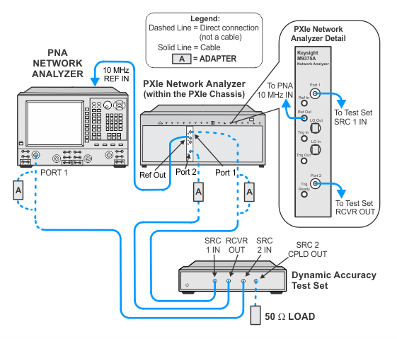
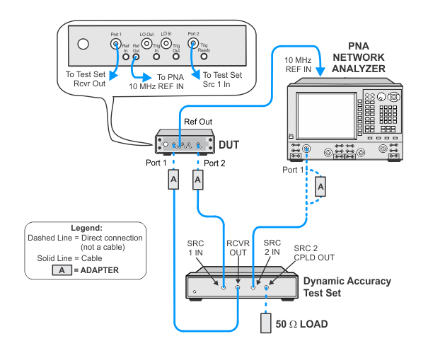
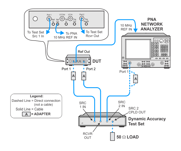
Connections and Setup Procedures
Click on the drop-down links below to view setup images.
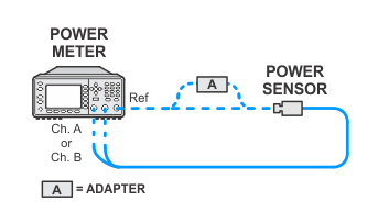
Flexible power sensor channel assignment
This test will use flexible power sensor channel assignment that will identify the channel that a power sensor is connected to using the ability of "smart" sensors such as the N848xA series power sensors to report their full model and serial number. Therefore it is important to keep the power sensor on the channel where it was calibrated throughout the test procedures.