Equation 1

where all values are in dB. This equation will return the source power accuracy error in dB. If values are measured in linear terms, the equation can be written as:
Equation 2
This test quantifies the leveled power accuracy of the source versus frequency and ALC power setting. This specification applies over the full specified frequency range and full ALC range of the VNA. Testing each frequency point at each power level listed in the driving data would collect more data than what is feasible for a report. Therefore, the procedure will test all frequency values listed in the driving data at one power level (Preset power), and the full ALC range at a subset of frequencies.
At each test point, the source delivers power to a matched load while the power is measured and compared to the desired power level. The difference, or error, between the measured result and the desired power level represents the power level accuracy. A mathematical expression for this specification is:
Equation 1
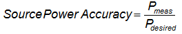
where all values are in dB. This equation will return the source power accuracy error in dB. If values are measured in linear terms, the equation can be written as:
Equation 2
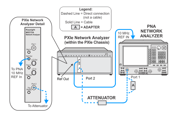
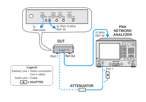
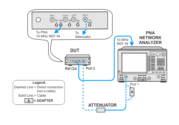
To measure the power level accuracy of the VNA source, the source must be connected to a receiver. Since the VNA source has high harmonic content, a broadband power sensor cannot be used to measure the source power. Therefore, a SmartCal procedure called PNAasPowerMeter will be used to make an external PNA behave as a tuned power meter. The data from the SmartCal can be recalled from a previous test providing it's within four hours and the cable and attenuator connections have not been disturbed. Otherwise, the PNAasPowerMeter calibration procedure must be repeated.
Refer to Connections and Setup Procedures below for more information.
Click here for troubleshooting help.
|
|
TME will present a prompt that offers the user the choice to perform the calibration before starting the test at hand even if it's been within the allowed timeframe. Existing data can be used, if available. For troubleshooting, it is recommended to re-do the calibration especially if you are unsure if the adapter/cable/attenuator setup has been disturbed or disconnected. |
|
Test Equipment |
Recommended Models1 |
|---|---|
|
PNA network analyzer |
N5245B |
|
Attenuator, 10 dB |
8493C Option 010 |
|
Power meter 2 |
N1914A |
|
Power sensor 2 |
N8485A |
|
ECal module, 3.5 mm |
N4691D3 Option M0F |
|
Cable, 3.5 mm (m) to 3.5 mm (f) |
8121-2111 |
|
Adapter, 3.5 mm (f) to 3.5 mm (f) |
83059B |
|
|
|
To ensure best test results, use a good quality cable, adapter, and attenuator. Do not disturb the adapter/cable/attenuator setup attached to the PNA. Because the data from the PNAasPowerMeter calibration is stored and re-used by other tests, it is important that the most accurate data is achieved by following these practices. |
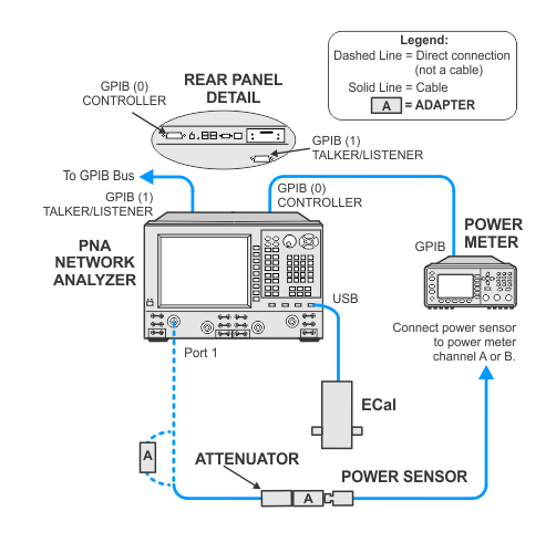
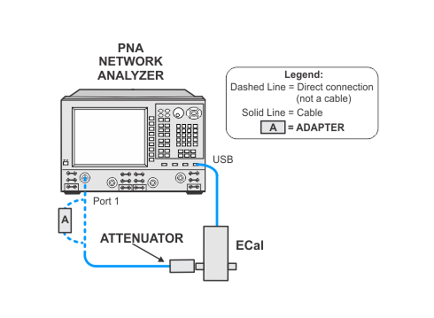
This test uses a procedure called PNAasPowerMeter. A calibrated PNA receiver will be used as the filtered power level measurement standard. This receiver is a combination of a PNA with a cable connected to one of the test ports, and a 10 dB attenuator connected to the end of the test cable. The attenuator is used to minimize the measurement uncertainty due to the VNA port mismatch.
Unless recalling stored data from a previously run PNAasPowerMeter procedure, or if the cable, adapter, or attenuator attached to the PNA has been disturbed, this process must be performed prior to running the test.
This test will use flexible power sensor channel assignment that will identify the channel that a power sensor is connected to using the ability of "smart" sensors such as the N848xA series power sensors to report their full model and serial number. Therefore it is important to keep the power sensor on the channel where it was calibrated throughout the test procedures.
Click on the drop-down links below to view setup images.
|
|
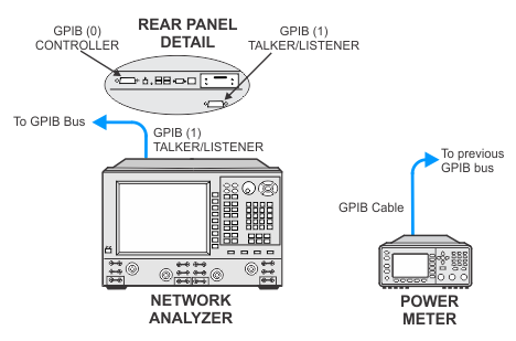
The illustrations below show details of the GPIB connections of the power meter and the PNA. After the power sensor calibration, the PNA will directly control the power meter through the GPIB cable. In order for this to occur, be sure when making the GPIB connections to:
|