IF Frequency Response is one component of the analyzer Error Vector Magnitude (EVM) specification.
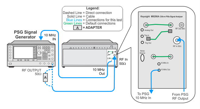
In this test a 1.5 GHz, –10 dBm signal is applied to the analyzer. This input level establishes a mixer level of –20 dBm. A reference amplitude is taken with the input signal centered at the analyzer center frequency. The analyzer center frequency is then changed to set the input signal at various offsets within the FFT span of interest. At each offset frequency the amplitude is measured by the analyzer. The amplitude difference between the offset frequency and the reference frequency is reported as the IF Frequency Response. This measurement is performed in IQ analyzer mode, so the span is also the FFT width. This measurement is performed for the standard 10 MHz IF path (if Option B25 is installed the bandwidth is 25 MHz).
|
Test Equipment |
Recommended Model Number1 |
|---|---|
|
Microwave signal generator #1 |
PSG models |
|
Cable, BNC (m) to SMB (f) |
8121-2063 |
|
Coaxial cable, 3.5 mm (m) to 3.5 mm (m) |
11500E |
|
Adapter, 3.5 mm (f) to 3.5 mm (f)
|
83059B |
|
Adapter, 2.4 mm (f) to 3.5 mm (f)
|
11901B |
|
