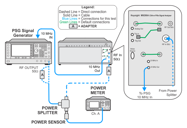
This test verifies that the analyzer meets its specification for input related spurious responses. In this test, the source is connected to the RF Input and set for the spur frequency. The source amplitude is measured using a power meter. The source frequency is then moved to the frequency location that will create the spur at the analyzer center frequency. The amplitude of the source is kept consistent by using the power meter. The analyzer then measures the spurious response at the spur frequency.
|
Test Equipment |
Recommended Model Number1 |
|---|---|
|
Microwave signal generator #1 |
PSG models |
|
Power meter |
N1914A |
|
Microwave power sensor |
N8485A CFT |
|
Power splitter |
11667B |
|
Cable, BNC (m) to SMB (f) |
8121-2063 |
|
Cable, Coaxial, 3.5 mm (m) to 3.5 mm (m) |
11500E |
|
Adapter, 3.5 mm (m) to 3.5 mm (m)2 |
83059A |
|
Adapter, 3.5 mm (f) to 3.5 mm (f)
|
83059B |
|
Adapter, 2.4 mm (f) to 3.5 mm (f)
|
11901B |
|
Adapter, 3.5 mm (f) to Type-N (m)
|
08485-60005 |
|