


 Object Model
Syntax
| Visual Basic (Declaration) | |
|---|---|
Public MustInherit Class Digital Inherits RemotableObject Implements IPropertyInfo, IPropertyInfo2, IRemoteNotifyPropertyChanged, IRemoteNotifyPropertyInfoChanged | |
| C# | |
|---|---|
public abstract class Digital : RemotableObject, IPropertyInfo, IPropertyInfo2, IRemoteNotifyPropertyChanged, IRemoteNotifyPropertyInfoChanged | |
| C++/CLI | |
|---|---|
public ref class Digital abstract : public RemotableObject, IPropertyInfo, IPropertyInfo2, IRemoteNotifyPropertyChanged, IRemoteNotifyPropertyInfoChanged | |
Remarks
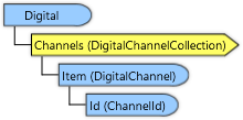
This class and the DigitalChannel class are used to setup an 89600 measurement using data from an Keysight Logic Analyzer. The user must have previously set up the logic analyzer configuration using Logic Analyzer Application.
The Logic Analyzer configuration consists of one or more Analysis Modules and any optional software Tools attached to the modules.
The outputs of analysis modules and tools are groups of digital signals called buses. The names and configuration for data modules, tools, and buses can be freely assigned using the Logic Analyzer application.
Measurement Procedure
To analyze data from a Logic Analyzer application using the Vector Signal Analyzer
- First connect the VSA to a Logic Analyzer application (using the Hardware object)
- Select the measurement input data module using the DigitalChannel.DataModule property. You only need to select this for one channel. See note below.
- (optional) If software tools are connected to the data module in the logic analyzer configuration, you may select a software tool for each channel using the DigitalChannel.DataTool property. See note below.
- Use the DataPart property to specify the data format (e.g., real, I and Q on separate buses, interleaved I/Q, etc.)
- Specify the data bus or buses for each measurement channel using the DigitalChannel.DataBusPart1 and .DataBusPart2 properties.
- Use the DataSign property to select the binary data sign convention.
- (optional) Specify scaling using the DigitalChannel.DataScalePart1 and .DataScalePart2 properties.
- Set the SampleRate property to represent the data sample rate. This is not the bus data rate but the sample rate when viewed as a discrete communications signal (e.g. its sample rate at a DAC input or an ADC output).
- (optional) Use the Center property to associate a center frequency with the data. The default is 0.
Requirements
Target Platforms: Windows 11 Professional or Enterprise; Windows 10 Professional, Enterprise, or Education (64-bit)