Error Vector Time (Digital Demod)
When is enabled, the trace shows the time-domain error vector trace data results. This trace contains the computed error vectors between corresponding symbol points in the I/Q measured and I/Q reference signals.
The following graphic shows the calculation of the error vector magnitude (EVM Error vector magnitude (EVM): A quality metric in digital communication systems. See the EVM metric in the Error Summary Table topic in each demodulator for more information on how EVM is calculated for that modulation format.) for a symbol point. The diagram on the right shows how the error vector itself is calculated.
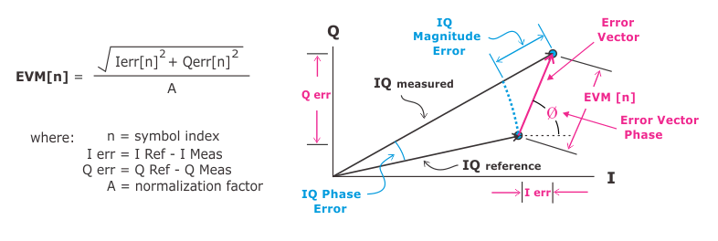
If normalization is OFF, the error vector magnitude is shown in units of Volts (normalization factor = 1). If normalization is ON, the error vector magnitude is expressed as a percentage of a normalization factor. See Normalize IQ Traces for more information.
You can set the trace data format to view Error Vector Magnitude, Error Vector Phase, just the I error, or just the Q error.
Trace Data Formats
It is important to remember that the Error Vector Time trace is a time record made up of complex, time-domain data. Each point in the time record has two components: I and Q. To make sense of the data, select an appropriate trace data format ( drop-down list).
- Linear Mag: EVM (Error Vector Magnitude)
- Real(I): I component of the error vector
- Imag(Q) : Q component of the error vector
- Wrap Phase: Error Vector Phase error
If the is different than expected, see Troubleshooting.