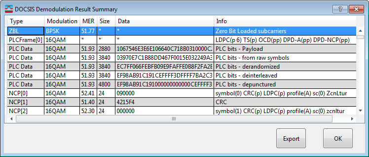
Demod Result (DOCSIS 4.0 Downstream)
The button opens the table.
In general, if the VSA software is not configured to match the signal presented for analysis so that the VSA can successfully demodulate the signal, this table may have fewer entries or no entries at all.
is only available when BER Analysis is enabled.

Data Types
The following five types of data may be presented in the table.
ZBL
ZBL is the first entry of the table – indicates the MER of any ZBL (zero-bit-loaded) subcarriers in the analysis interval. If there are no ZBL subcarriers in the analysis interval, this entry will not appear in the table.
PLC Search Results
(only available if mode=AUTO and a valid PLC is found)
PLC search results shows the results of VSA’s attempt to demodulate the PLC channel and find the three critical parameter blocks needed to decode the remainder of the signal. These blocks are:
- : OFDM Carrier Description
- : Data Profile Descriptor for modulation profile A
- : Data Profile Descriptor for NCP subcarriers
Each PLC frame consists of the following parameter blocks and other information in the PLC that may be decoded:
- : The PLC search results show the status (pass or fail) of LDPC decoding for each frame found, along with the number of iterations of the LDPC decode algorithm. Examples:
- LDPC(p 6) – indicates LDPC decoding passed (p) after 6 iterations
- LDPC(f 20) – indicates LDPC decoding failed (f) after 20 iterations
- : The time-stamp entry indicates the pass/fail status of the checksum on the time-stamp message – if such a message is found in the decoded PLC frame. Example:
- TS(p) – indicates the transmitted checksum matches the computed checksum, otherwise it will be TS(f)
- , , and : These blocks have both a header checksum and a message block checksum, so there are two pass/fail indicators. Example:
- DPD-A(pp) indicates a DPD-A block was found, and both checksums matched as expected
For demodulation to proceed past the PLC stage (to full-bw demodulation with NCP and code-words and MER/BER results) all three of critical parameter blocks must be successfully decoded (OCD, DPD-A, DPD-NCP). If they are not, switch PLC Settings from to and enter the parameters on the GUI.
PLC Data (Decode Stream Information)
This information is available if at least one PLC frame was successfully decoded. The full decoding chain is presented for validation purposes.
- : The first line is the actual payload after all decoding.
- : The second line indicates the bits extracted from the demodulated 16QAM symbols of the PLC.
- : The third line shows the second line after the de-randomization process.
- : The fourth line shows the de-randomized bits after the de-interleaving process.
- : The fifth line shows the de-interleaved bits after de-puncturing. These bits are then sent to the LDPC decoder, and the output is the first line ( PLC bits – payload).
NCP Information
This is the log of the NCP information recovered from the signal. Each symbol analyzed has at one or two NCP blocks. There are two types of NCP blocks: some contain information about where a code word starts in that symbol and how to demodulate and decode that code word; the second type contains a CRC. The CRC block is always the NCP block in the symbol. The CRC block is used to validate the successful demodulation of all the previous NCP blocks in that symbol.
All NCP blocks contain 24 bits of data. The CRC block uses all 24 bits for the CRC. The info NCP blocks have the following data:
- The modulation profile for the code word (A,B,C … P) (4 bits)
- Seven bits of flags (Z,C,N,L,T,U,R) – see specification for the definitions of these bits, in the table the bit is represented by UPPER CASE if the bit is a 1 and lower case if the bit is a 0 (Z=1, z=0, C=1, c=0, N=1,n=0, L=1, l=0, T=1, t=0, U=1, u=0, R=1, r=0)
- The index of the first subcarrier of the code-word – a 13 bit integer
The table also shows the symbol offset (from the beginning of the analysis interval), the LDPC decode status (p/f), and the CRC status (p/f) for each info NCP
Codeword information
This section shows the decoded code words. For each code word, the modulation type, MER, and size is shown, along with the data bits (in hexadecimal). The error statistics are also shown:
- LDPC status (pass/fail, and number of iterations)
- BCH status (pass/fail) – BCH(p) means that the code-word is successfully decoded.
- Error bits (number of error bits before BCH decoding)
The number of data bits can be quite high. For ease of visibility, only the first parts are shown in the Data column of the table, followed by an ellipsis (…). If an ellipsis is present, you can access the full content of the data field by using the button and saving the table to an external file.
Export
saves the Demodulation Result Summary data to a .csv file that can be opened in many tools including Matlab and Excel.
When you click the Export button in the DOCSIS Demodulation Result Summary dialog, it will export a .csv file in addition to previously exported files. It contains MER results over all subcarriers and symbols.
The format of output .csv file is as follows:
MER per subcarrier per symbol:
Subcarrier Index, Symbol #0, Symbol# 1, …, Symbol #126, Symbol #127
===============================================================
Subcarrier #0
…
…
Subcarrier #(N-1)
Subcarrier index ranges from 0 to FFT-1 (4095 or 8191).
See Also
