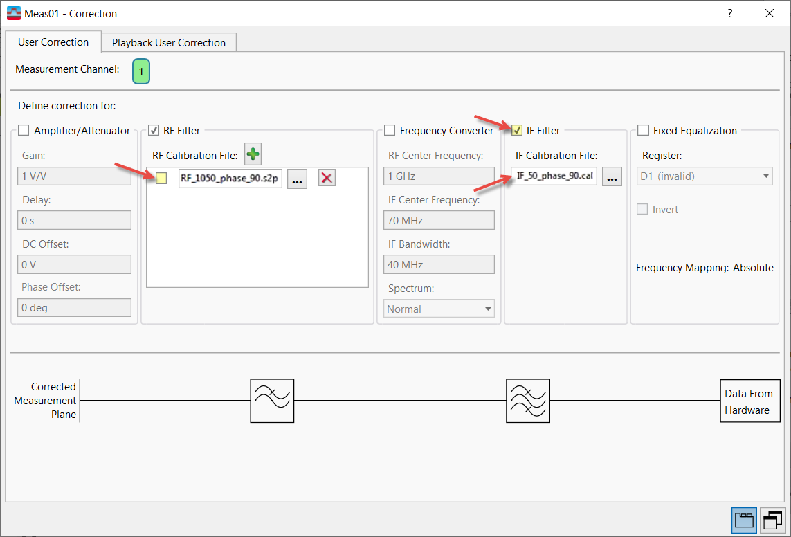
RF Filter (User Correction, Playback User Correction)
Menu Path:
corrections are applied to external hardware (User Correction) or recorded playback data (Playback User Correction).
(User Correction) compensates for the frequency response for the following external devices:
- an external filter or amplifier device placed between the DUT Device under Test: An acronym used to describe some type of electrical apparatus connected to test instrumentation. The apparatus can range from a single component to a complex subsystem such as a mobile phone, base station or MSC. and analyzer hardware.
- the preselection filter of an external downconverter that is used to extend the frequency range of the analyzer hardware.
- any network added to the VSA input that does not translate frequency.
does not characterize the added device—the user must supply the calibration file or group of files—but includes the device user correction data to the internal frequency-dependent corrections, so that the measurement accurately represents the signal at the input of the added device.
Using RF Filter
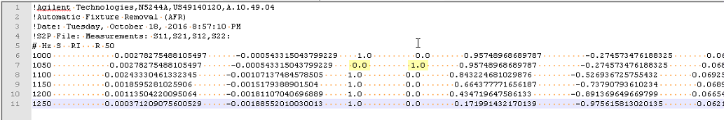
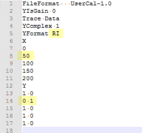
To use , one or more device frequency response calibration files must be created over the entire measurement frequency range and with sufficient frequency resolution to describe the shape of the response. The RF Radio Frequency: A generic term for radio-based technologies, operating between the Low Frequency range (30k Hz) and the Extra High Frequency range (300 GHz). Filter file format can be either .cal and .s2p. For details on how to generate the file, see User calibration file format. The name of the file and the directory it is stored in are unrestricted.
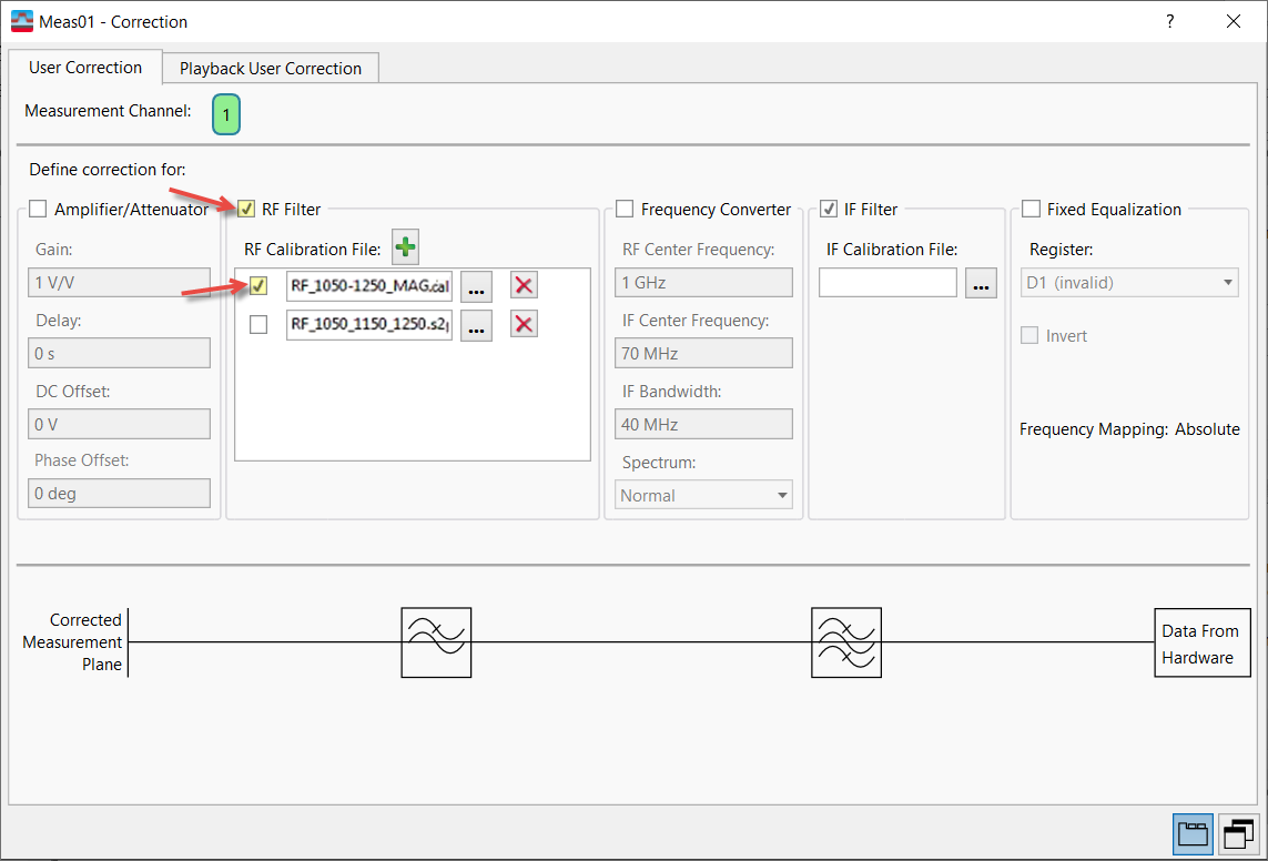
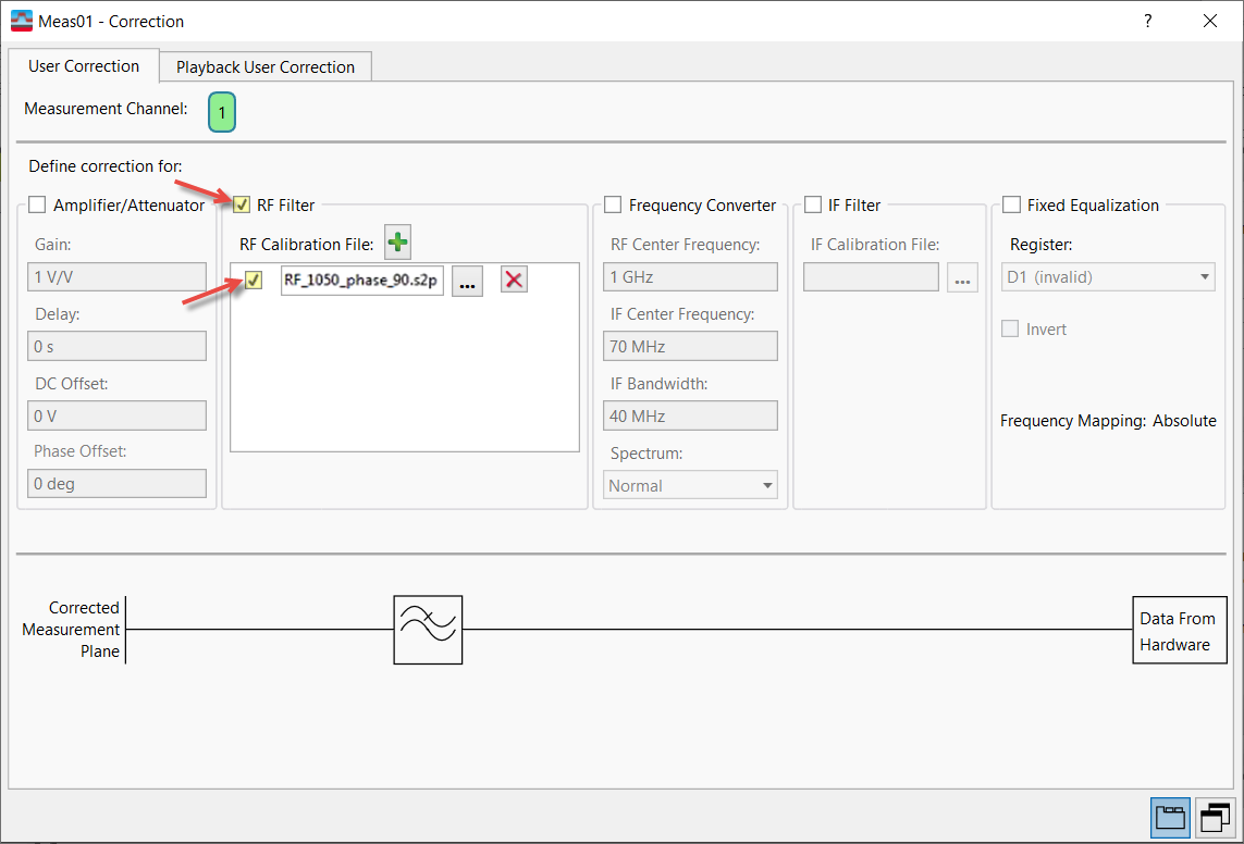
To enable the RF Filter user correction, select the to apply the user corrects too and then select the check box.
Next import the device RF Filter calibration file (or files); click the browse button ![]() to locate and load the calibration file. The compensation can be applied
independent from other external devices.Separate user correction calibration files can be used for each measurement channel. You can use the parameter to independently apply user corrections for each separate measurement channel.
to locate and load the calibration file. The compensation can be applied
independent from other external devices.Separate user correction calibration files can be used for each measurement channel. You can use the parameter to independently apply user corrections for each separate measurement channel.
When is selected, the VSA reads the file that describes the frequency response and selects the portion of the frequency response that is appropriate to the current measurement’s center frequency and span. For frequencies between those tabulated in the calibration file, values are interpolated and used to construct a compensating filter. When the VSA center frequency or span is changed, the calibration file data that corresponds to the new span is used.
User Corrections supports two correction file types: .cal and .s2p:
.cal files
- If a .cal file doesn't include phase information (e.g., dB), only magnitude correction is applied with no inverse.
- If a .cal file includes phase information (e.g., RI), magnitude (no inverse) and phase will be interpolated to fit the input signal and applied.
.s2p files
- .s2p files include phase information. Data from the file is inverted before it is applied to the signal.
Examples
RF Magnitude Correction Example
RF Magnitude Correction Example
The following example is non-hardware specific. It uses two RF Filter files--one in .cal format and one in .s2p format--to adjust the magnitude of two of three tones in a multitone signal. The effects of the corrections on the signal are additive; however, the VSA's internal algorithm inverts the .s2p file's data before interpolation.
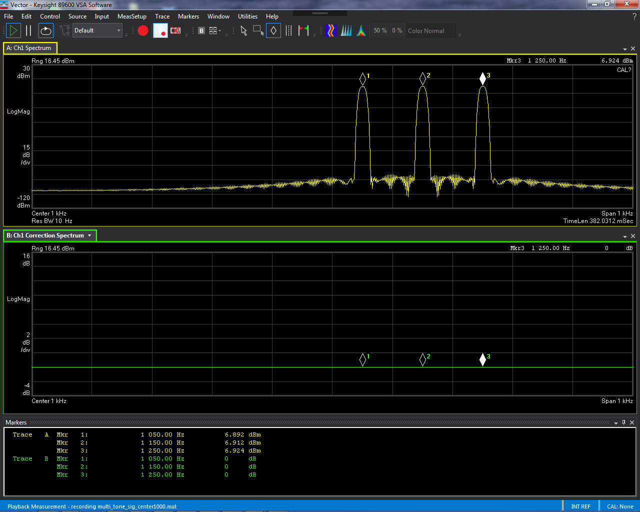
Uncorrected multitone signal with three tones of equal magnitude:
Two RF Magnitude correction files are loaded into the list of RF Filter correction files (one .cal file and one .s2p file).
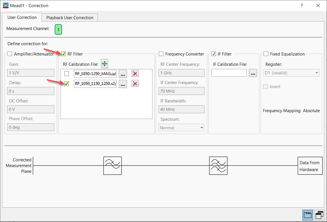
Only the .cal file (RF_1050-1250_MAG.cal) is selected to be included as a part of the signal corrections:
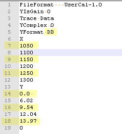
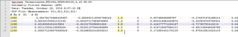
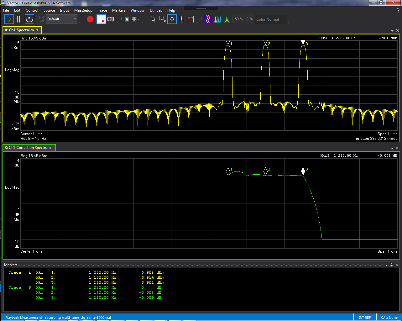
The .cal correction file adds a separate correction magnitude (in dB) to each of the three tones in the multitone signal (1050Hz: 0.0 dB, 1150 Hz: 9.54 dB, 1250 Hz: 13.97 dB):
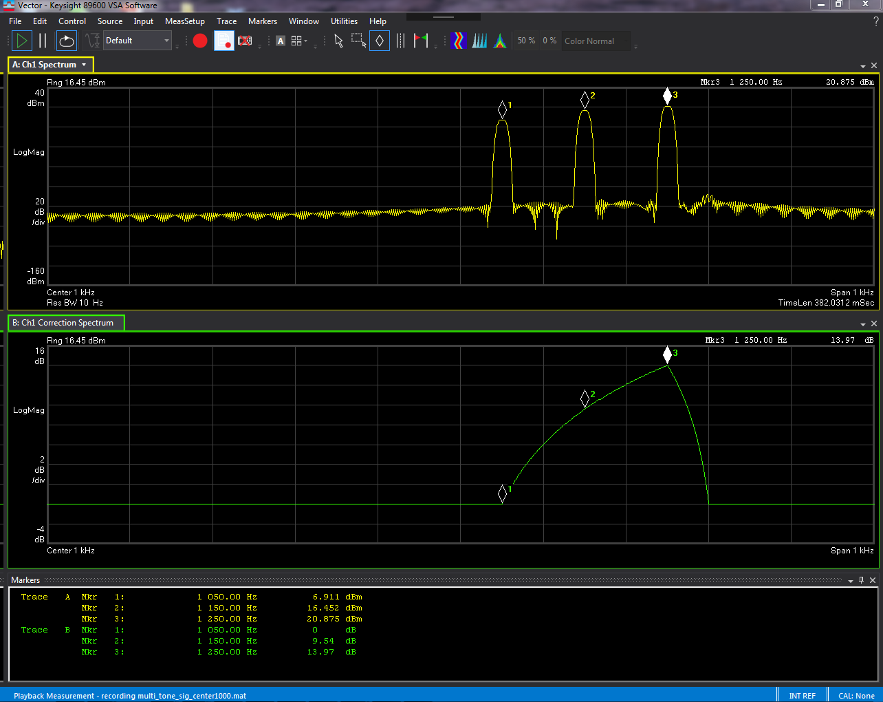
The resulting measurement traces reflect only the .cal correction:
Only the .s2p file (RF_1050_1150_1250.s2p) is selected to be included as a part of the signal corrections:
The .s2p correction file adds a separate correction magnitude factor to each of the three tones in the multitone signal (1050Hz: 1, 1150 Hz: 3, 1250 Hz: 5).
For .s2p files, the VSA's internal algorithm inverts the data from the .s2p file before interpolation.
The resulting measurement traces reflect only the .s2p correction. Note that it is the inverse of the .cal correction:
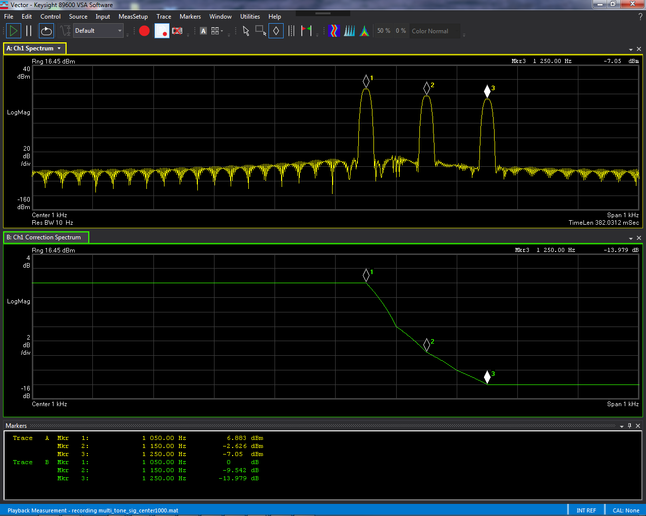
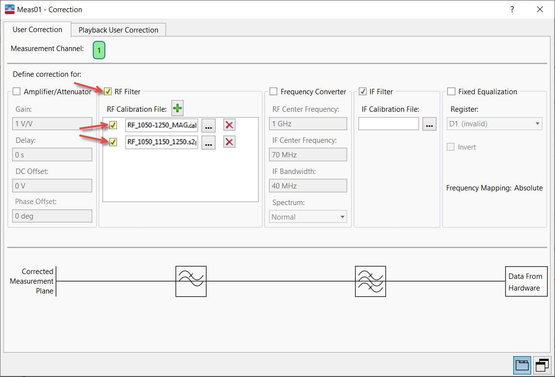
Both files on the list (RF_1050-1250_MAG.cal and RF_1050_1150_1250.s2p) are selected to be included as a part of the signal corrections:
Since both files apply the same amount of magnitude correction but the .s2p file's data is inverted, the two corrections effectively cancel each other and the resulting signal is essentially unchanged:
Phase Correction Example
The following phase correction example is non-hardware specific. It uses two files; however, one file is an RF Filter file in .s2p format, and one is an IF Filter file in .cal format. The effects of the corrections on the signal are additive; however, the VSA's internal algorithm inverts the .s2p file's data before interpolation.
Uncorrected signal:
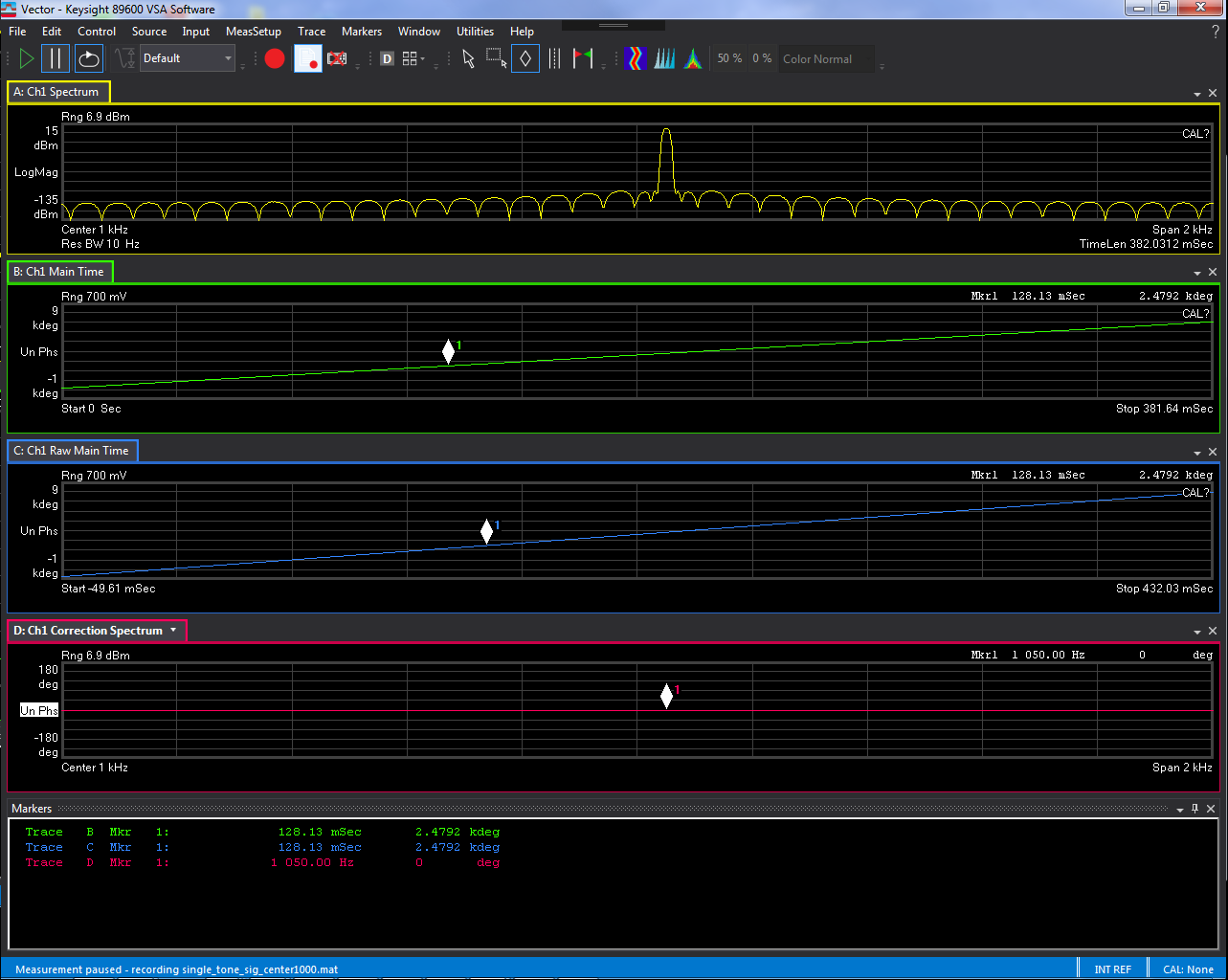
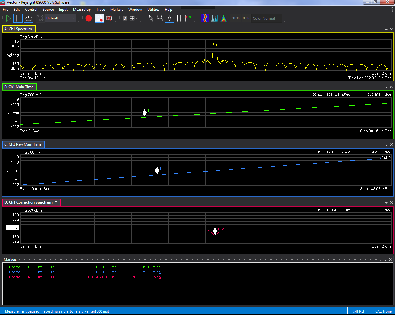
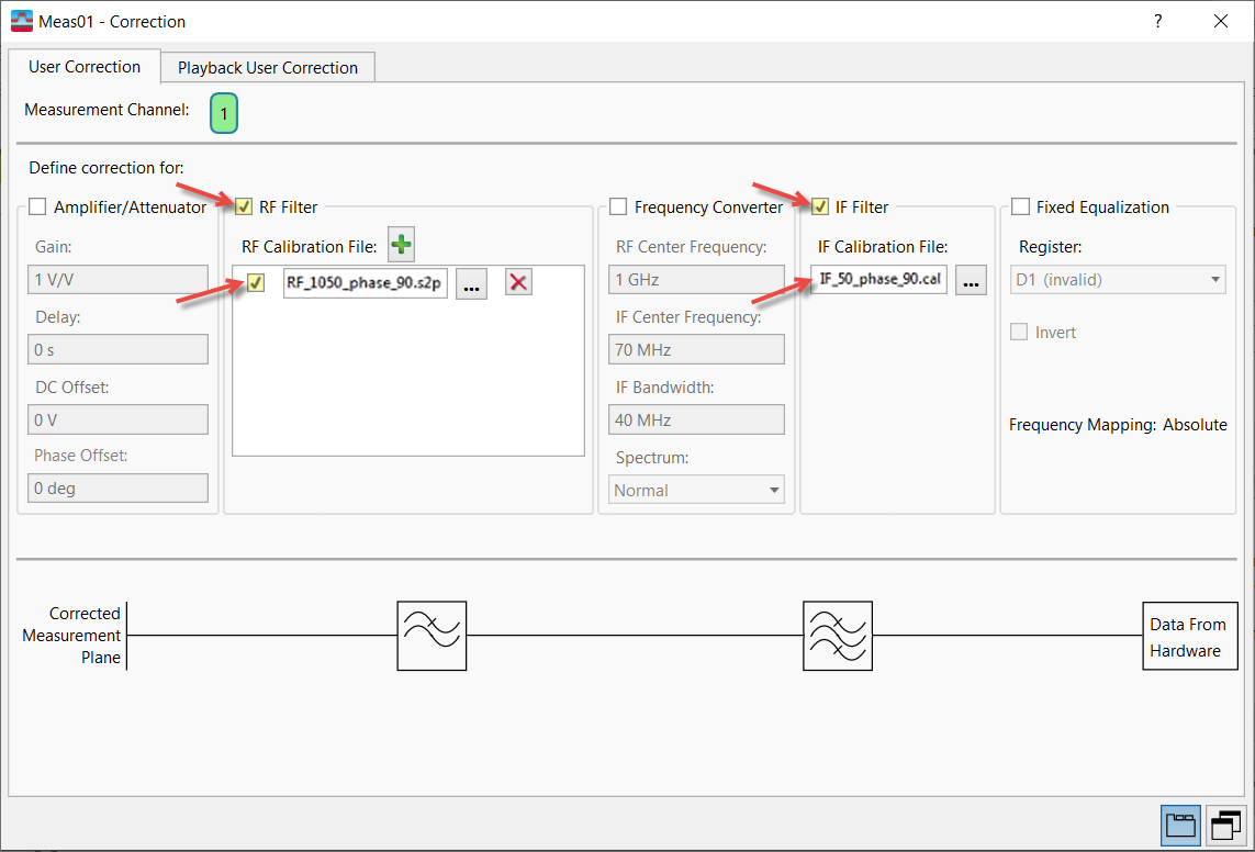
An .s2p file (RF_1050_phase_90.s2p) is loaded into the list of RF Filter correction files. The RF Filter file is selected to be included as a part of the signal corrections:
The .s2p RF correction file adjusts the phase of the tone at 1050 Hz by 90 degrees:
For .s2p files, the VSA's internal algorithm inverts the data from the .s2p file before interpolation.
The resulting measurement traces reflect only the .s2p correction. Note that it is the inverse of the correction file data (-90 deg):
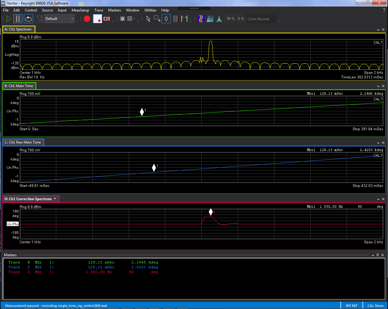
A .cal file (IF_50_phase_90.cal) is loaded into the list of IF Filter correction files.
The .cal file is selected and the .s2p file is deselected so that only the corrections in the .cal file will be applied:
The .cal IF correction file adds another 90 degrees of phase to the tone at 1050 Hz:
The resulting measurement traces reflect only the .cal correction:
Both correction files are selected (RF_1050_phase_90.s2p and IF_50_phase_90.cal) to be included as part of the signal corrections:
The resulting measurement traces reflect the additional corrections:
Since both files apply the same amount of phase correction but the .s2p file's data is inverted, the two corrections effectively cancel each other and the final result is nearly no change to the input signal:

See Also