Making an ACP Measurement (Markers)
The ACP Adjacent Channel Power: The power from a modulated communications channel that leaks into an adjacent channel. This leakage is usually specified as a ratio to the power in the main channel, but is sometimes an absolute power. marker easily performs generic Adjacent Channel Power measurements. The ACP marker properties configures the reference channel and up to 5 separate adjacent channels. The ACP marker also provides a complete set of data results consisting of the ACP marker trace data readouts and an associated table.
The typical measurement process comprises selecting a trace data display that has a spectrum data result, enabling the ACP Marker, configuring the ACP marker reference channel and adjacent channels, and viewing the measurement results in the corresponding ACP Summary table.
To perform an ACP measurement, follow these steps:
-
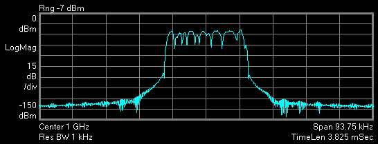
First select a trace that shows spectrum data and make it the active trace by clicking on it. In this example, the trace is selected as the active trace.

The ACP marker only applies to trace data with spectrum data results, other demod trace data is not allowed. The check box is disabled for non-spectrum trace data results.
ACP Markers can be used with Math Function traces as long as the X-axis data units are "Hz".
-
Enable the marker for the currently selected trace.
Click and select the check box.
-
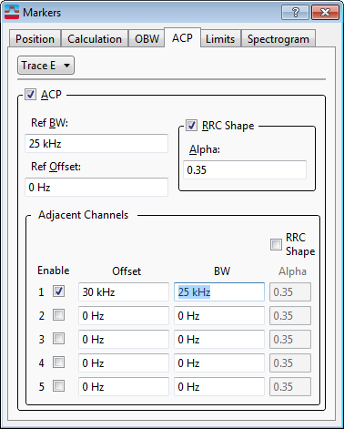
Next configure the reference channel.
Specify the reference channel bandwidth and offset from the center frequency.
-
Specify the reference channel BW in the text box (25 kHz kiloHertz: A radio frequency measurement (one kilohertz = one thousand cycles per second). in this example).
-
Select the check box for a Root Raised Cosine shape applied to the reference channel marker or to enable the RRC shape on the adjacent channels. Specify the filter alpha value in the textbox.

-
-
Select and configure each adjacent channel to include in the ACP measurement.
This can be up to five adjacent channels. Specify the offset frequency for each adjacent channel and the BW. For a Root Raised Cosine shape applied to any adjacent channel markers, select the checkbox. Specify an alpha for each adjacent channel. The RRC Shape checkbox must be selected to activate the adjacent channel alphas. A setting of zero for the alpha gives the same results as disabling the Root Raised Cosine shape for that adjacent channel. Then select enable for each adjacent channel included the measurement:
From the dialog box, specify the adjacent channel frequency and for each adjacent channel in the measurement:
-
Specify the offset frequency in the text box and the bandwidth in the text box for each adjacent channel.
This example configures one adjacent channel with Offset = 25 kHz, BW = 18 kHz
-
Select the Enable 1 checkbox.
-
Data Results
The ACP marker measurement determines the reference channel power, from 1 to a maximum of 5 adjacent (upper and lower) channel powers (ACP), and the ACP for each of the adjacent (upper and lower) channels. In order to show all these data results, the analyzer provides the ACP marker readouts and an additional table:
-
ACP marker readouts: Provides the reference channel power and the ACP for one offset adjacent (lower and Upper) channel.
-
"ACP Summary table" trace data: Provides a complete set of ACP marker measurement results.
ACP marker readouts
When the marker is selected for a spectrum trace data result, the ACP marker readout provides these results:
-
[dBm deciBels referenced to a milliWatt: dB relative to 1 milliwatt dissipated in the nominal input impedance of the analyzer] Total absolute power in the reference channel.
-
[dB] ACP for the Lower Offset "X" Channel, where "X" is the channel number. The marker readout will only show results for one offset adjacent channel.
-
[dB] ACP for the Upper Offset "X" Channel, where "X" is the channel number. The marker readout will only show results for one offset adjacent channel.
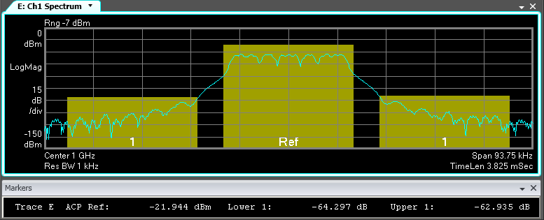
The following example display shows the ACP marker measurement and readouts as applied to our test signals. This measurement is configured to determine the ACP for 1 offset adjacent channel.

The ACP marker trace results identify the reference channel as "ACP Ref" and the offset adjacent channels with their respective channel number. The display also uses highlighted proportional background bars to show the relative powers and bandwidths for all measured channels. This example shows measurement results for the reference channel and 1 adjacent (upper and lower) channel.
ACP Summary Table trace data
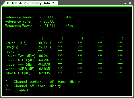
There is also an table trace data result that is available for each ACP marker trace data result. The table provides a complete set of ACP marker results for both the reference channel (bandwidth, alpha, and power) and each adjacent (upper and lower) channel included in the measurement (offset frequency, bandwidth, alpha, lower and upper power and ACPR Adjacent Channel Power Ratio - A measurement of the amount of interference, or power, in the adjacent frequency channel. ACPR is usually defined as the ratio of the average power in the adjacent frequency channel (or offset) to the average power in the transmitted frequency channel. ACPR is a critical measurement for CDMA transmitters and their components. It describes the amount of distortion generated due to nonlinearities in RF components. The ACPR measurement is not part of the cdmaOne standard., and maximum ACPR). For more information, see ACP Summary Table trace data help.
The table trace data only applies to trace displays with spectrum data results and marker selected.
To show the table trace data, select the trace data that corresponds to the same trace display that shows the ACP marker measurement results.
In the following example, the trace data will be shown in trace display A for the "ACP Marker" results in trace display B.
-
Make trace A the active display.
-
Show the table result in trace A for the trace B spectrum data:
Click

This example shows the table results for the Trace E ACP marker trace data.
See Also
