Spectrum Map
in the Synchronous Acquisition Mode, the Spectrum Map provides a graphical representation of the spectral usage (center frequency and span) of each measurement in a Shared group.
The combined center frequencies and spans of measurements in a Shared group must fit within the maximum analysis bandwidth of the shared measurement hardware.
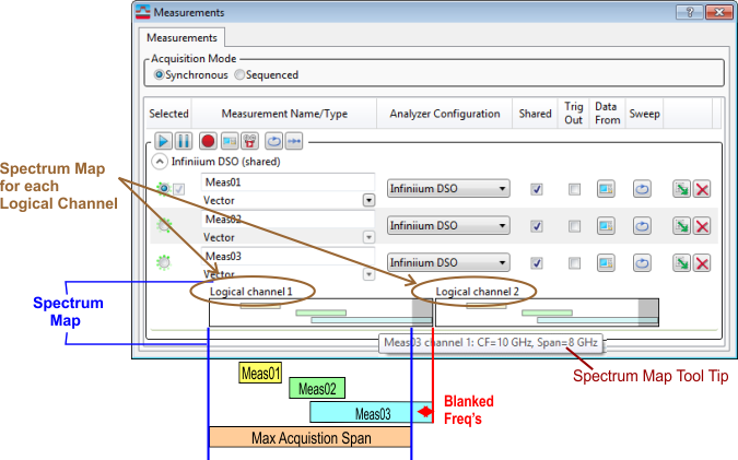
The spectrum map shows a separate box for each logical input channel in the input channel configuration that in use. The width of each box represents the larger of 1) the analysis bandwidth of the channel or 2) the combined measurement spectrum of the set of measurements sharing this hardware. The white background represents the maximum analysis bandwidth of the channel. If the combined measurement spectrum of the measurements exceeds the analysis bandwidth of the channel, data exceeding the channel's analysis bandwidth cannot be measured. This is represented by a gray background in the spectrum map. These regions falling outside the channel bandwidth are blanked on any traces showing spectrum data for the affected measurement.
Within the box for each channel, there is one colored bar for each shared measurement that is using that channel. Note that not all measurements are necessarily using all channels (see the Custom Channel Configuration dialog topic). Each bar represents the span and center frequency of that measurement relative to the analysis bandwidth of the channel.
Descriptive tooltips are available for each of the measurement bars, as well as for the blanked and non-blanked background of each logical channel.
Understanding Blanked Frequencies
Even when the measurement center frequencies fit within the logical channel analysis bandwidth of the measurement hardware, the combination of measurement spans could exceed the hardware's analysis bandwidth. In this case, the VSA equally distributes the analysis bandwidth between the two farthest center frequencies and blanks the frequencies that fall outside the hardware's analysis bandwidth.
The blanked areas of the spectrum are shown with the color gray. The following illustration shows two measurements configured as follows:
- Meas01 - Center = 980 MHz Megahertz: A unit of frequency equal to one million hertz or cycles per second., Span = 10 MHz
- Meas02 - Center = 1 GHz Gigahertz: A frequency measurement which equals one billion hertz., Span = 10 MHz
![]()
The total analysis bandwidth required is (1 GHz + 5 MHz) - (980 MHz - 5 MHz) = 30 MHz, which is 5 MHz wider than the supported analysis bandwidth (25 MHz). Therefore 2.5 MHz of the spectrum is blanked on either side of the spectrum map.
For spectrum traces, the annotations will show the requested Center/Span settings for a measurement, but the blanked part of the spectrum will not be shown on the trace.
See Also