Use Case: Uplink + Downlink
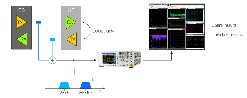
When you want to analyze the uplink and downlink signals for a wireless format, you can configure the 89600 VSA to simultaneously perform uplink and downlink modulation analysis. This is accomplished by combining the uplink and downlink signals and feeding the combined signal into a instrument (Phase-Synchronous (Shared) Acquisition).
To set up this scenario, combine the uplink and downlink signals with a power combiner and connect the composite signal to the measurement hardware. Next, add two measurements to the VSA, link them to the same measurement hardware, and configure the demodulator settings appropriately.
The combination of the uplink and downlink signals must fit within the analysis bandwidth of the measurement hardware.
The base station (BS Base Station - The equipment on the network side of a wireless communications link. The base station contains the tower, antennas and radio equipment needed to allow wireless communications devices to connect with the network.) and user equipment (UE User Equipment (e.g. cell phone)) are shown in a common bit-error rate (BER Bit Error Ratio - A ratio of the number of errors to data bits received on a digital circuit.) test where the UE sends the received bits back to the base station for comparison with transmitted bits.
Benefits
- Truly simultaneous - uplink and downlink measurement results can be compared for the same frame
- Relative measurements - metrics such as timing and power can be compared between uplink and downlink
- TDD Time Division Duplex: A duplexing technique dividing a radio channel in time to allow downlink operation during part of the frame period and uplink operation in the remainder of the frame period. or FDD Frequency Division Duplex: A duplex scheme in which uplink and downlink transmissions use different frequencies but are typically simultaneous. - a measurement can be performed on either signals that use time-domain duplexing (TDD) or frequency-domain duplexing (FDD).
You can also perform a loosely synchronized, uplink/downlink measurement with multiple instruments (Time-Synchronous acquisition). To do this, instead of combining the uplink and downlink signals, connect each to a separate instrument, and connect the uplink and downlink VSA measurements to the corresponding instruments. Then configure External Triggering and use the Trig Out parameter in the Measurements dialog. See Making a Triggered Multi-Measurement for more information.
See Also