About Multiple Numerologies (5G NR/5G-Advanced)
The VSA software's 5G NR/5G-Advanced demodulator supports the use of multiple (mixed) numerologies in a single BWP. This topic provides information about working with and understanding mixed numerologies.
- Impact on trace result data
- Impact on Measurement Interval and Measurement Offset
- Multiple Numerology Limitations
Impact on trace result data
-
For Traces with points on subcarrier and symbol locations (e.g., Error Vector Time/Spectrum, and Allocation trace, and Meas/Ref), behavior changes when multiple numerologies are active.
-
Symbol represents the shortest duration numerology.
-
Subcarrier represents the narrowest bandwidth numerology.
-
When multiple numerologies are active, the Error Vector Spectrum and Error Vector Time traces will show varying point widths representing relative time/frequency occupancy for each channel.
Impact on Measurement Interval and Measurement Offset
When mixed numerologies are used in a measurement, there is a difference in scaling between the measurement and some rendered traces. The Detected Allocations Time, Error Vector Time, and Error Vector Spectrum traces will be affected by this. However, Error Vector Spectrum is only affected by the markers. When we place a marker on the Error Vector Spectrum trace, the symbols are scaled based on the largest numerology.
The VSA measurement scales carriers in the frequency domain by the smallest numerology defined in the signal; however, the trace drawing engine scales symbols in the time domain by the largest numerology in the signal. Traces need to use the largest numerology to ensure that symbols won’t have any half steps between signals (e,g., symbol 4.5 or something similar). Therefore, when using traces to determine the correct measurement offset and interval to set in symbols, you must convert from trace symbols to measurement symbols by dividing by the (maxSCS / minSCS) ratio. For example, if the maximum numerology is 60kHz and the minimum numerology is 30kHz, after inputting the measurement offset and interval in symbols, the trace will display two times what was defined in the offset or interval. This is expressed as:
TraceSymbols = SymbolsDefinedInMeasOffsetOrInterval * (maxSCS/minSCS).
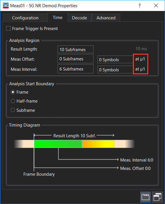
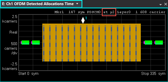
The numerology used by Meas Offset and Meas Interval is displayed to the right of the parameters for use in the calculation. Similarly, the numerology used by the trace drawing engine is displayed with the marker data at the top of the trace. Examples of each are shown below.
Numerology for Measurement Offset and Measurement Interval

Numerology for scaling traces

Multiple Numerology Limitations
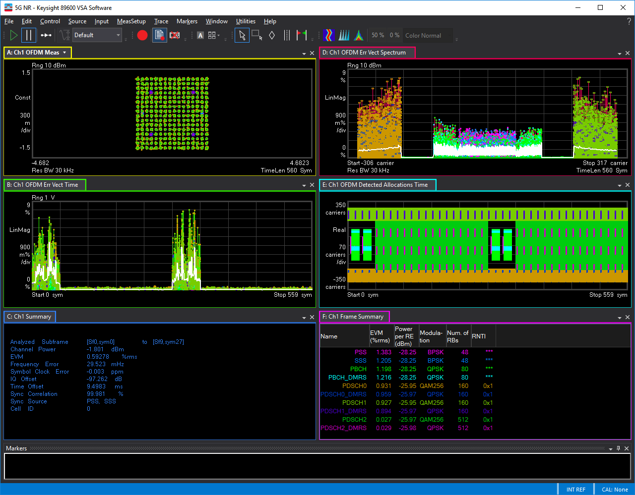
Multi-numerology measurement capability is limited to scenarios where a single numerology is present in each symbol. If a measurement is attempted with multiple numerologies present within the same symbol, the configuration is allowed, but elevated EVM Error vector magnitude (EVM): A quality metric in digital communication systems. See the EVM metric in the Error Summary Table topic in each demodulator for more information on how EVM is calculated for that modulation format. will be observed. The elevation will be particularly significant at the spectrum interface between numerologies, but it noticeably affects EVM across the entire spectrum.
Results may look similar to this:

In some cases, making separate narrowband measurements of SS/PBCH instead of a wideband measurement may help to provide more accurate SS/PBCH EVM and Power/Phase results. To make a narrowband measurement that just spans the SS/PBCH, change the measurement center close to the SS/PBCH center and set the span only to include the SS/PBCH signal so that the BWP with different numerology is filtered.
After changing the measurement center frequency to the SS/PBCH center, make sure to adjust the SS/PBCH RB offset and kSSB accordingly. See RB Offset(15kHz|60kHz) and kSSB(15kHz|60kHz) for more information.
See Also
5G NR/5G-Advanced Demod Properties Dialog Box
