Input Extensions (InfiniiVision/Streamline Series Oscilloscopes)
are the measurement hardware configuration and setup parameters that apply to the Keysight 89600 VSA with Keysight InfiniiVision/Streamline Series Oscilloscopes.
To modify a hardware parameter, open the Input Extension dialog (tab), click the parameter name and specify the value. For True/False values, a selected check box sets the value to True. A cleared check box sets the value to False.
Click to preset all input extension parameters across all logical instruments and channels.
Hardware Configuration Parameters:
InfiniiVision HD3 Series MSO Oscilloscopes
|
Parameter |
Value |
Default |
|---|---|---|
|
String |
<blank> |
|
|
True / False |
False |
|
|
Double |
NaN (when DDC is not active) |
|
|
NotApplied / Ddc/ HighResolution |
NotApplied |
|
|
Driver / Measurement |
Driver |
|
|
FullRate / FullRateDdc / Minimize / UserRate |
FullRate; FullRateDdc if hardware-based DDC is supported |
|
|
Double |
NaN |
|
|
Real |
1E+09 |
|
|
String |
<blank> |
CustomTrigCommand
CustomTrigCommand is used to set trigger parameters on the InfiniiVision HD3 Series Oscilloscopes that cannot be set directly from the 89600 user interface. This parameter enables the user to take advantage of the InfiniiVision HD3 Series oscilloscopes extensive trigger conditioning and pattern capability.
A sequence of SCPI commands can be entered, beginning with ":TRIG" and separated by semicolons, into the CustomTrigCommand dialog box. The commands will be transmitted to the oscilloscope when the Configure dialog box is closed when CustomTrigType is true. The trigger type selected in the Trigger tab of the Input Properties dialog box (Input > Trigger) is overridden when the commands are transmitted. SCPI Query commands are not supported.
CustomTrigType
When CustomTrigType is true, the trigger types can be configured by entering SCPI commands in the CustomTrigCommand hardware parameter. When this parameter is false, the trigger type is selected in the 89600 software ( tab).
Hardware DDC Sample Rate
Hardware DDC Sample Rate displays a read only value and is only available for oscilloscope models with hardware DDC.
When the DDC is active, this field will show the DDC sample rate.
When the DDC is not active, this field will show NaN.
Hardware DDC Status
Hardware DDC Status displays a read only value and is only available for oscilloscope models with hardware DDC.
When oscilloscope Spectrum Analysis (DDC) is active for hardware digital downconversion, this field will show DDC applied.
When oscilloscope High Resolution acquisition mode is active for hardware digital downconversion, this field will show High Resolution applied.
When hardware digital downconversion is not active, this field will show Not applied. Hardware digital downconversion is not applied if the oscilloscope does not have the necessary options present, FullRateDdc is not the selected sample mode, frequency limits are not met, the channel is a differential channel, or the instrument is simulated.
ResampleLocation
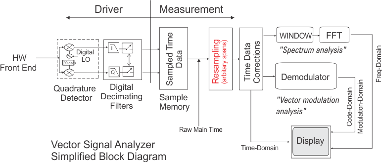
The 89600 VSA software automatically resamples the scope input data to satisfy the data sample requirements for the current VSA measurement span. This minimizes the amount of data required and used for a particular measurement. The large data capture memory size capability of the InfiniiVision series oscilloscopes can exceed the 89600 VSA software internal data limit. The "ResampleLocation" parameter takes advantage of these longer time lengths by resampling in the 89600 software's driver for the InfiniiVision scopes (this occurs before the 89600 measurement system block). For more information on resampling and VSA theory of operation, see Application Note 150-15 Keysight Vector Signal Analysis Basics (see Product Literature). There are two ResampleLocation modes: Measurement mode and Driver (default) mode:
mode:
When ResampleLocation is set to Measurement, the resampling of the input time data is implemented in the 89600 VSA "Measurement" system block which bypasses the "Driver" digital decimating filter system block (see the following VSA system block diagram). In "Measurement" mode, the current measurement is limited to 8.2 M pts of the scope input data. This in turn limits the VSA maximum time Record Length and either the Search Length or Result Length depending on the type of measurement.
"Measurement" mode limits the current VSA measurement to 8.2 M pts of the scope input data.
mode (default):
When the ResampleLocation is set to Driver, the resampling of the input time data is implemented in the 89600 VSA software – InfiniiVision HD3 scope "driver" digital decimating filter system block (see preceding VSA system block diagram). In "Driver" mode, the current measurement input data is not limited to 8.2 M pts of scope data. However, there are differences in some of the 89600 VSA operation and data results:
Driver mode VSA operating differences:
- Some events may not be seen in the 89600 software traces since the raw scope data is not available to view. For example, a signal that is outside the measurement span may not be visible in 89600 traces but may still cause a trigger to occur since the scope's triggering is before the sampler.
- The Raw Main Time trace is changed to Resampled Raw Main Time when resampling occurs in the Driver.
- Recordings will store the resampled data instead of the raw scope data.
- Channel triggering may be harder to set up as the scope hardware triggers before the resampler and the data in the Resampled Raw Main Time trace is at the output of the resampler.
SampleMode
FullRate Mode
When the SampleMode is set to FullRate, the oscilloscope sample rate is set to the minimum sample rate necessary to acquire signals at the scope's full bandwidth.
There is a trade-off when using this mode. At the full sample rate, the maximum time record length is less than when using lower simple rates. If a longer Main Time (or Result Length for digital demodulation) is needed for more resolution in the frequency domain, then select either Maximize, Minimize or UserRate instead.
Any limitation to Main Time (or Result Length) will be indicated by the inability of the software to increase the Main Time or decrease RBW Resolution Band Width (RBW or ResBW): specifies the minimum frequency bandwith that two separate frequency spectra can be resolved and viewed seperately. For FFT (digital) based VSA's the process is equivalent to passing a time-domain signal through a bank of bandpass filters, whose center frequencies correspond to the frequencies of the FFT bins. For a traditional swept-tuned (non-digital) spectrum analyzer, the resolution bandwidth is the bandwidth of the IF filter which determines the selectivity. when Number of Frequency Points is increased.
FullRateDdc Mode (HD3 models with firmware version 10.05 or later)
When the SampleMode is set to FullRateDdc, the full ADC Analog-to-Digital Converter sample rate of the oscilloscope is used. The hardware-based digital down converter (DDC) is used when possible with Zoom time data. Channel bandwidth high-definition (HD) is used with Baseband time data. FullRateDdc is an active selection if the connected scope supports the oscilloscope DDC option and/or HD mode. Otherwise, it will be grayed out and not selectable.
The mode of operation used by the oscilloscope (DDC, High Resolution mode, or normal) is based upon Zoom vs Baseband, Center Frequency, and Span.
When using the FullRateDdc sample mode, the ResampleLocation will be limited to the Driver selection (the Measurement selection is disabled).
The Hardware DDC Sample Rate input extension parameter in the VSA software indicates when the path through the real-time hardware-based DDC in the oscilloscope or channel bandwidth high-definition (HD) mode is active and being used, and if used, displays the output sample rate or DDC or High Resolution mode.
FullRateDdc sample mode uses HD mode for Baseband. Otherwise, normal mode is used for Zoom.
When FullRateDdc sample mode uses HD mode for Baseband, the number of bits of vertical resolution increases as bandwidth decreases at discreet values.
Minimize Mode
When the SampleMode is set to Minimize, the scope's sample rate is set to the smallest value possible for proper IF subsampling with the current center frequency / span combination. Depending on the center frequency / span combination, the IF subsample rate can be less than the full sample rate available in the scope. When it is much less than the full rate, significant increases in Main Time are possible.
Minimize mode gives the largest values of Main Time on the operating region curves. However, it produces less spreading of the out-of-band alias exposure zones. Use Minimize when there are no out-of-band signals and the longest Main Time values are desired.
UserRate Mode
When the SampleMode is set to UserRate, the sample rate is specified using the UserSampleRate input extension.
Sample Rate Actual
Sample Rate Actual displays a read only value of the actual oscilloscope sample rate in Sa/sec.
UserSampleRate
UserSampleRate selects the scope sample rate when SampleMode is set to UserRate. The actual sample rate selected will be the highest sample rate that is less than or equal to the user requested sample rate, up to and including the FullRate sample rate. By controlling the scope sample rate, you can directly influence the update rate of the VSA. This is because sample rate directly affects the number of points the scope must transfer to the VSA. Certain measurements can be made significantly faster by limiting the scope sample rate due to reduced data transfer requirements.
UserSampleRate can also be used to increase the maximum acquisition time available from the scope by specifying a lower sample rate. A lower sample causes fewer samples to be taken per second, which means a longer time record can fit in the capture memory of the scope.
The following sample rates are possible when using the InfiniiVision HD3 Series Oscilloscopes with the 89600 Software:
3.2 GSa/s, 1.6 GSa/s, 800 MSa/s, 640 MSa/s, 400 MSa/s, 320 MSa/s, 200 MSa/s, 100 MSa/s, 80 MSa/s, 64 MSa/s, 50 MSa/s, 40 MSa/s, 32 MSa/s, 20 MSa/s, 10 MSa/s, 8 MSa/s, 6.4 MSa/s, 5 MSa/s, 4 MSa/s, 3.2 MSa/s, 2 MSa/s, 1 MSa/s, 800 kSa/s, 640 kSa/s, 500 kSa/s, 400 kSa/s, 200 kSa/s, 100 kSa/s, 80 kSa/s, 64 kSa/s, 50 kSa/s, 40 kSa/s, 20 kSa/s, 10 kSa/s, 8 kSa/s, 64 kSa/s, 5 kSa/s, 4 kSa/s, 2 kSa/s
UserSCPIPreset
UserSCPIPreset is useful for setting parameters on the InfiniiVision HD3 Series Oscilloscope that cannot be set directly from the 89600 user interface.
SCPI commands can be entered separated by semicolons. SCPI Query commands are not supported.
Verify that none of the commands conflict with the normal operation of the software.
The VSA software may not undo the effect of these commands when the parameter is changed or an application preset is done. For commands affected by a *RST, you can disconnect and then reconnect after removing the command or after doing an application preset in order to undo the effect of the command.
Whenever the 89600 VSA needs to preset the oscilloscope, it will send these user SCPI commands followed by other commands from the VSA. Be aware that the VSA preset will overwrite conflicting user SCPI commands.
To enter SCPI preset commands, follow these steps:
-
Make sure that the Infiniivision HD3 oscilloscope is specified as the Logical Instrument in the Analyzer Configuration. Click Utilities > Hardware > Configurations.
-
On the Input > HW-Specific (Extensions) tab, type in the SCPI commands separated by semicolons in the UserSCPIPreset parameter text box.
For detailed information on SCPI commands for the InfiniiVision HD3 Series oscilloscopes, refer to oscilloscope programming documentation.
All other Infiniivision/Streamline Series Oscilloscopes
|
Parameter |
Value |
Default |
|---|---|---|
|
String |
<blank> |
|
|
True / False |
False |
|
|
Measurement / Driver |
Driver |
|
|
FullRate / UserRate |
FullRate |
|
|
Double |
NaN |
|
|
True / False |
False |
|
|
Real |
1E+09 |
|
|
String |
<blank> |
CustomTrigCommand
CustomTrigCommand is used to set trigger parameters on the InfiniiVision series oscilloscopes that you cannot set directly from the 89600 user interface. This parameter enables you to take advantage of the InfiniiVision oscilloscope's extensive trigger conditioning and pattern capability.
A sequence of SCPI commands can be entered, beginning with ":TRIG" and separated by semicolons, into the CustomTrigCommand dialog box. The commands will be transmitted to the oscilloscope when the Configure dialog box is closed when CustomTrigType is true. The trigger type selected in the Trigger tab of the Input Properties dialog box (Input > Trigger) is overridden when the commands are transmitted. SCPI Query commands are not supported.
CustomTrigType
When CustomTrigType is true, the trigger types can be configured by entering SCPI commands in the CustomTrigCommand hardware parameter. When this parameter is false, the trigger type is selected in the 89600 software ( tab).
ResampleLocation
The 89600 VSA software automatically resamples the scope input data to satisfy the data sample requirements for the current VSA measurement span. This minimizes the amount of data required and used for a particular measurement. The large data capture memory size capability of the InfiniiVision series oscilloscopes can exceed the 89600 VSA software internal data limit. The "ResampleLocation" parameter takes advantage of these longer time lengths by resampling in the 89600 software's driver for the InfiniiVision scopes (this occurs before the 89600 measurement system block). For more information on resampling and VSA theory of operation, see Application Note 150-15 Keysight Vector Signal Analysis Basics (see Product Literature). There are two ResampleLocation modes: Measurement mode and Driver (default) mode:
mode:
When ResampleLocation is set to Measurement, the resampling of the input time data is implemented in the 89600 VSA "Measurement" system block which bypasses the "Driver" digital decimating filter system block (see the following VSA system block diagram). In "Measurement" mode, the current measurement is limited to 8.2 M pts of the scope input data. This in turn limits the VSA maximum time Record Length and either the Search Length or Result Length depending on the type of measurement.
"Measurement" mode limits the current VSA measurement to 8.2 M pts of the scope input data.
mode (default):
When the ResampleLocation is set to , the resampling of the input time data is implemented in the 89600 VSA software - scope "driver" digital decimating filter system block (see preceding VSA system block diagram). In "Driver" mode, the current measurement input data is not limited to 8.2 M pts of scope data. However, there are differences in some of the 89600 VSA operation and data results:
Driver mode VSA operating differences:
- Some events may not be seen in the 89600 software traces since the raw scope data is not available to view. For example, a signal that is outside the measurement span may not be visible in 89600 traces but may still cause a trigger to occur since the scope's triggering is before the sampler.
- The Raw Main Time trace is changed to Resampled Raw Main Time when resampling occurs in the Driver.
- Recordings will store the resampled data instead of the raw scope data.
- Channel triggering may be harder to setup as the scope hardware triggers before the resampler and the data in the Resampled Raw Main Time trace is at the output of the resampler.
SampleMode
When the SampleMode is set to FullRate, the scope is set to the minimum sample rate necessary to acquire signals at the scope's full bandwidth. In some cases, this may not be the highest sample rate the scope supports. When this parameter is set to UserRate, the UserSampleRate parameter is enabled.
Sample Rate Actual
Sample Rate Actual displays a read only value of the actual oscilloscope sample rate in Sa/sec.
UnlockFrontPanel
If UnlockFrontPanel is True, the scope front panel is enabled. If UnlockFrontPanel is False, the instrument front panel is locked.
Setting the value to True can interfere with communication between other applications and other GPIB instruments.
Take care not to change parameters that will interfere with 89600 measurements, such as data sample rate, sweep time, or enabled channels.
UnlockFrontPanel is useful for diagnostic purposes or to change scope parameters that the 89600 software does not set.
4000X-Series scopes: For 4000-X series models, the scope display and front-panel updates are set to "OFF" when Unlock FrontPanel is set to "False". Therefore, the scope display will not necessarily indicate the current 89600 VSA scope state settings.
UserSampleRate
The UserSampleRate specifies the scope sample rate. The actual measurement sample rate is the highest sample rate that is less than or equal to the user requested sample rate, up to and including the scope's Full Rate sample rate. By controlling the scope sample rate, you can directly influence the update rate of the 89600 VSA. This is because sample rate directly affects the number of points the scope must transfer to the VSA. Certain measurements can be made significantly faster by limiting the scope sample rate, which reduces the data transfer requirements.
UserSampleRate can also be used to increase the maximum acquisition time available from the scope by specifying a lower sample rate. A lower sample causes fewer samples to be taken per second, which means a longer time record can fit in the capture memory of the scope. See the InfiniiVision 6000/7000 Series Oscilloscopes with 89600B VSA Software (PN 5990-6820EN) Application Note for information on signal aliasing.
The sample rates vary depending on the scope capture memory and whether the scope is operating in Half Channel or Full Channel mode.
- :
- Half Channel mode used in 1 channel measurements
- Full Channel mode used in 2 channel measurements
- :
- Half Channel mode: On four-channel scopes, the channels are combined in pairs (Channels 1 and 2 are paired, Channels 3 and 4 are paired). When only 1 channel in a pair is used, the scope operates in Half Channel mode.
Full Channel modes: When both channels in a channel pair are used, the scope operates in Full Channel mode.
When using 4 channel scopes and the channel configuration is set to , the VSA uses scope input Channel 1 and Channel 3.
The following table summarizes the Scope input channel number and mode to the 89600 VSA input channel mapping.
| Scope Input Ch to VSA Input Ch Mapping | |||
|---|---|---|---|
|
|
|
Scope |
|
|
All 2-Channel models |
1 channel 2 channels |
Half Channel Full Channel |
Chan 1 Chan 1 and 2 |
|
All 4-Channel models |
1 channel 2 channels 3 channels 4 channels I + jQ Dual I + jQ |
Half Channel Half Channel Full Channel Full Channel Half Channel Full Channel |
Chan 1 Chan 1 and 3 Chan 1, 2, and 3 Chan 1, 2, 3, and 4 Chan 1 and 3 Chan 1, 2, 3, and 4 |
Oscilloscope Sample Rate vs Capture Memory
The following tables specify the possible sample rates when using the various supported Oscilloscope models with the 89600 Series software.
1000 X-Series: Sample Rate vs Memory
The following tables specify the possible sample rates when using the 1000 X-Series Oscilloscopes with the 89600 Series software.
1. The scope model is listed next to its
maximum sample rate.
2. The scope can sample at all sample rates listed below its maximum.
Memory: 1M
|
Mode: Half Channel |
Mode: Full Channel |
||
|---|---|---|---|
|
Scope Model |
Sample Rate |
Scope Model |
Sample Rate |
|
All 1000 X-Series
|
2 GSa/S 1 GSa/S 500 MSa/S 250 MSa/S 100 MSa/S 50 MSa/S 25 MSa/S 10 MSa/S 5 MSa/S 2.5 MSa/S 1 MSa/S 0.5 MSa/S |
All 1000 X-Series
|
2 GSa/S 1 GSa/S 500 MSa/S 250 MSa/S 100 MSa/S 50 MSa/S 25 MSa/S 10 MSa/S 5 MSa/S 2.5 MSa/S 1 MSa/S 0.5 MSa/S |
3000 X-Series: Sample Rate vs Memory
The following tables specify the possible sample rates when using the 3000 X-Series Oscilloscopes with the 89600 Series software.
1. The scope model is listed next to its
maximum sample rate.
2. The scope can sample at all sample rates listed below its maximum.
Memory: 2M
|
Mode: Half Channel |
Mode: Full Channel |
||
|---|---|---|---|
|
Scope Model |
Sample Rate |
Scope Model |
Sample Rate |
|
All 3000 X-Series, except 310x models
|
4 GSa/S 2 GSa/S 1 GSa/S 500 MSa/S 200 MSa/S 100 MSa/S 50 MSa/S 20 MSa/S 10 MSa/S 5 MSa/S 2 MSa/S 1 MSa/S |
All 3000 X-Series, except 310x models
|
2 GSa/S 1 GSa/S 500 MSa/S 250 MSa/S 100 MSa/S 50 MSa/S 25 MSa/S 10 MSa/S 5 MSa/S 2.5 MSa/S 1 MSa/S
|
|
Mode: Half Channel |
Mode: Full Channel |
||
|
Scope Model |
Sample Rate |
Scope Model |
Sample Rate |
|
Only 310x model 3000 X-series scopes
|
5 GSa/S 1 GSa/S 500 MSa/S 200 MSa/S 100 MSa/S 50 MSa/S 20 MSa/S 10 MSa/S 5 MSa/S 2 MSa/S 1 MSa/S |
Only 310x model 3000 X-Series scopes
|
2.5 GSa/S 500 MSa/S 250 MSa/S 100 MSa/S 50 MSa/S 25 MSa/S 10 MSa/S 5 MSa/S 2.5 MSa/S 1 MSa/S
|
Memory: 4M
|
Mode: Half Channel |
Mode: Full Channel |
||
|---|---|---|---|
|
Scope Model |
Sample Rate |
Scope Model |
Sample Rate |
|
All 3000 X-Series, except 310x models
|
4 GSa/S 2 GSa/S 1 GSa/S 400 MSa/S 200 MSa/S 100 MSa/S 40 MSa/S 20 MSa/S 10 MSa/S 4 MSa/S 2 MSa/S 1 MSa/S |
All 3000 X-Series, except 310x models
|
2 GSa/S 1 GSa/S 500 MSa/S 200 MSa/S 100 MSa/S 50 MSa/S 20 MSa/S 10 MSa/S 5 MSa/S 2 MSa/S 1 MSa/S
|
|
Mode: Half Channel |
Mode: Full Channel |
||
|
Scope Model |
Sample Rate |
Scope Model |
Sample Rate |
|
Only 310x model 3000 X-series scopes
|
5 GSa/S 2.5 GSa/S 1.25 GSa/S 1 GSa/S 200 MSa/S 100 MSa/S 40 MSa/S 20 MSa/S 10 MSa/S 4 MSa/S 2 MSa/S |
Only 310x model 3000 X-Series scopes
|
2.5 GSa/S 1.25 GSa/S 625 MSa/S 500 MSa/S 100 MSa/S 50 MSa/S 20 MSa/S 10 MSa/S 5 MSa/S 2 MSa/S |
3000T X-Series: Sample Rate vs Memory
The following tables specify the possible sample rates when using the 3000T X-Series Oscilloscopes with the 89600 Series software.
1. The scope model is listed next to its
maximum sample rate.
2. The scope can sample at all sample rates listed below its maximum.
Memory: 2M and 4M
|
Mode: Half Channel |
Mode: Full Channel |
||
|---|---|---|---|
|
Scope Model |
Sample Rate |
Scope Model |
Sample Rate |
|
All 3000T X-Series
|
5 GSa/S 2.5 GSa/S 1.25 GSa/S 1 GSa/S 313 MSa/S 200 MSa/S 100 MSa/S 40 MSa/S 20 MSa/S 10 MSa/S 4 MSa/S 2 MSa/S |
All 3000T X-Series
|
2.5 GSa/S 1.25 GSa/S 625 MSa/S 500 MSa/S 156 MSa/S 100 MSa/S 50 MSa/S 20 MSa/S 10 MSa/S 5 MSa/S 2 MSa/S 1 MSa/S |
4000 X-Series: Sample Rate vs Memory
The following tables specify the possible sample rates when using the 4000 X-Series Oscilloscopes with the 89600 Series software.
1. The scope model is listed next to its
maximum sample rate.
2. The scope can sample at all sample rates listed below its maximum.
|
Mode: Half Channel |
Mode: Full Channel |
||
|---|---|---|---|
|
Scope Model |
Sample Rate |
Scope Model |
Sample Rate |
|
All 4000 X-series scopes
|
5 GSa/S 2.5 GSa/S 1.25 GSa/S 1 GSa/S 200 MSa/S 100 MSa/S 40 MSa/S 20 MSa/S 10 MSa/S 4 MSa/S 2 MSa/S |
All 4000 X-series scopes
|
2.5 GSa/S 1.25 GSa/S 625 MSa/S 500 MSa/S 100 MSa/S 50 MSa/S 20 MSa/S 10 MSa/S 5 MSa/S 2 MSa/S |
6000 X-Series: Sample Rate vs Memory
The following tables specify the possible sample rates when using the 6000 X-Series Oscilloscopes with the 89600 Series software.
1. The scope model is listed next to its
maximum sample rate.
2. The scope can sample at all sample rates listed below its maximum.
|
Mode: Half Channel |
Mode: Full Channel |
||
|---|---|---|---|
|
Scope Model |
Sample Rate |
Scope Model |
Sample Rate |
|
All 6000 X-series scopes |
20 GSa/S 10 GSa/S 5 GSa/S 2 GSa/S 1 GSa/S 500 MSa/S 400 MSa/S 250 MSa/S 200 MSa/S 80 MSa/S 40 MSa/S 20 MSa/S 4 MSa/S 2 MSa/S |
All 6000 X-series scopes |
10 GSa/S 5 GSa/S 2.5 GSa/S 1 GSa/S 500 MSa/S 250 MSa/S 200 MSa/S 125 MSa/S 100 MSa/S 40 MSa/S 20 MSa/S 10 MSa/S 2 MSa/S 1 MSa/S |
M924XA Series: Sample Rate vs Memory
The following tables specify the possible sample rates when using the M924XA Series PXIe Oscilloscopes with the 89600 Series software.
1. The scope model is listed next to its
maximum sample rate.
2. The scope can sample at all sample rates listed below its maximum.
|
Mode: Half Channel |
Mode: Full Channel |
||
|---|---|---|---|
|
Scope Model |
Sample Rate |
Scope Model |
Sample Rate |
|
All M924XA Series
|
5 GSa/S 2.5 GSa/S 1.25 GSa/S 1 GSa/S 313 MSa/S 200 MSa/S 100 MSa/S 40 MSa/S 20 MSa/S 10 MSa/S 4 MSa/S 2 MSa/S |
All M924XA Series
|
2.5 GSa/S 1.25 GSa/S 625 MSa/S 500 MSa/S 156 MSa/S 100 MSa/S 50 MSa/S 20 MSa/S 10 MSa/S 5 MSa/S 2 MSa/S 1 MSa/S |
P924XA Streamline Series: Sample Rate vs Memory
The following tables specify the possible sample rates when using the P924XA Streamline Series USB Oscilloscopes with the 89600 Series software.
1. The scope model is listed next to its
maximum sample rate.
2. The scope can sample at all sample rates listed below its maximum.
|
Mode: Half Channel |
Mode: Full Channel |
||
|---|---|---|---|
|
Scope Model |
Sample Rate |
Scope Model |
Sample Rate |
|
All P924XA Series
|
5 GSa/S 2.5 GSa/S 1.25 GSa/S 1 GSa/S 313 MSa/S 200 MSa/S 100 MSa/S 40 MSa/S 20 MSa/S 10 MSa/S 4 MSa/S 2 MSa/S |
All P924XA Series
|
2.5 GSa/S 1.25 GSa/S 625 MSa/S 500 MSa/S 156 MSa/S 100 MSa/S 50 MSa/S 20 MSa/S 10 MSa/S 5 MSa/S 2 MSa/S 1 MSa/S |
UserSCPIPreset
The UserSCPIPreset parameter is useful for setting parameters on the InfiniiVision Series Oscilloscope that you cannot set directly from the 89600 VSA user interface.
You can enter SCPI commands separated by semicolons. SCPI Query commands are not supported.
Verify that none of the commands conflict with the normal operation of the software.
The VSA software may not undo the effect of these commands when the parameter is changed or an application preset is done. For commands affected by a *RST, you can disconnect and then reconnect after removing the command or after doing an application preset in order to undo the effect of the command.
Whenever the VSA needs to preset the oscilloscope, it will send these user SCPI commands followed by other commands from the VSA. Be aware that the VSA preset will overwrite conflicting user SCPI commands.
To enter SCPI preset commands, follow these steps:
- Make sure that the InfiniiVision oscilloscope is specified as the Analyzer Configuration. Click Utilities > Hardware > Configurations.
- On the Input > HW-Specific (Extensions) tab, type the SCPI commands separated by semicolons in the UserSCPIPreset parameter text box.
For detailed information on SCPI commands for the InfiniiVision Series scopes, refer to scope programming documentation.
For more information about using a InfiniiVision Series DSO or MSO, see the InfiniiVision 6000/7000 Series Oscilloscopes with 89600B VSA Software (PN 5990-6820EN) Application Note .