LA and VSA Running on the LA Mainframe
This example will guide through the 89600 VSA and Logic Analyzer setups required to display a North American Digital Cellular (NADC North American Digital Cellular) signal acquired by the Logic Analyzer. This example is valid when both the Logic Analyzer application and the VSA application are running on the Logic Analyzer mainframe.
- Close the 89600 VSA.
- Start the Logic Analyzer application.
- Click File > Open.
- When the Open dialog box appears, click the Look in drop down menu and open %PROGRAMFILES%\Keysight\89600 Software <ReleaseVersion>\89600 VSA Software\LogicAnalyzer\demo nadc statedata.xml. The file demo nadc statedata.xml is a configuration and data file of an NADC signal that was installed with the 89600 software.
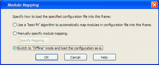
- Select Switch to "Offline" mode and load the configuration as-is when
the following dialog box appears. Click OK.
- Start the 89600 VSA.
- Create a new instrument connection:
- Click Utilities > Hardware > Instrument Manager.
- Click the "Add new instrument"
 button to open the Add/Edit New Instrument Address dialog box.
 - Click Custom LAN Local Area Network: A communications network that serves users within a local geographical area, typically over distances of around 100m. Wireless LANs use wireless communicaitons to network devices so there is no need for data cabling. and select AgtDigital from the Custom Model drop-down menu.
- Enter "localhost" as the Hostname, enter an optional Name, and click OK.
- The new logic analyzer connection should appear in the Instrument Manager list.
- On the Instrument Manager tab, click the "Rediscover Instruments"
 button so the VSA software discovers the new logic analyzer.
- Configure an Analyzer Configuration:
- Click Utilities > Hardware > Configurations.
- Click the "Add new configuration" button to open the New Hardware Configuration dialog box.
- Select the Logic Analyzer from the list of Possible Logical Instruments and drag it to the Configuration window.
- If there is more than one Logic Analyzer, select the specific Logic Analyzer to use for this configuration in step 2 of the New Hardware Configuration dialog box.
- In step 3, name the configuration. Click OK.
- Click OK.
- Select this Analyzer Configuration as the Current Analyzer Configuration in the Configurations tab.
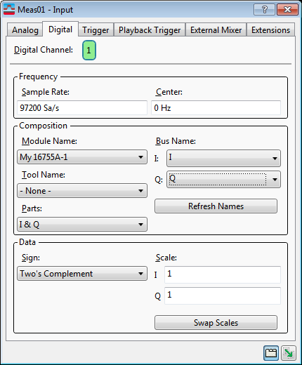
- Click Input > Digital. Type 97.2 kSa/Sec
in the Frequency Sample Rate text box. The Input Properties
dialog box Digital settings should now be the same as the
settings in the following Input Properties dialog box.
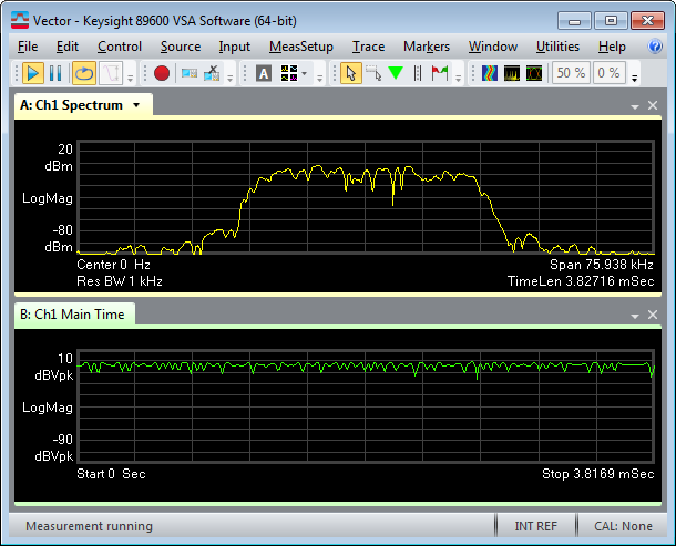
- Click the Play button on the 89600 VSA application.
The 89600 VSA display on the Logic Analyzer should look similar to the following screen shot.
If your 89600 VSA does not have option AYA, Vector Modulation Analysis, this is the end of the example. If your 89600 VSA does have option AYA, you can now digitally demodulate this signal.
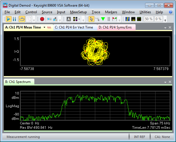
- Click MeasSetup > Demodulator > Digital Demod.
- Click MeasSetup > Demod Properties. In the Format Tab dialog box, click Preset to Standard > Cellular > NADC. In the Search Tab dialog box, clear the Pulse Search selection. Click Close.
The 89600 VSA display should now look similar to the following screen shot.