U9361 Calibration Module
The Keysight U9361 RCal family of comb calibrator modules are used to extend the reference plane of a calibrated X-Series signal analyzer from the front connector to the user's device under test (DUT Device under Test: An acronym used to describe some type of electrical apparatus connected to test instrumentation. The apparatus can range from a single component to a complex subsystem such as a mobile phone, base station or MSC.) at millimeter wave frequencies. U9361 RCal comb calibrators are available with various maximum frequencies.
Corrections Using the U9361 Comb Calibrator and X-Series Signal Analyzers
Typically, a user may have a DUT whose Tx output power is unknown, and there may be various RF Radio Frequency: A generic term for radio-based technologies, operating between the Low Frequency range (30k Hz) and the Extra High Frequency range (300 GHz). components that must be in place between the DUT and the analyzer, as shown below.
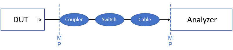
There's no nice way to bring the measurement plane (MP) from the RF input of the analyzer to the input of the coupler. Using the U9361 RCal Module, we can insert our known signal at the input of the coupler, shown as follows.
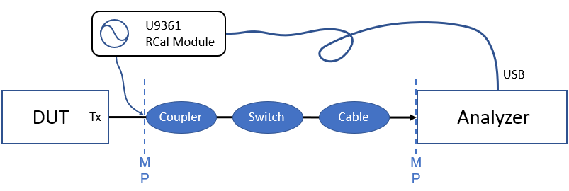
The frequency dependent path losses will now be characterized by the analyzer, such that any future measurements after the calibration step will be compensated for these losses. The U9361 RCal Module is connected to a USB port on the analyzer for both remote SCPI control and DC power. Unlike other comb calibrators, no additional external power supply is needed. The reference frequency for the U9361 RCal Module can be either internal or external. For good frequency stability, the U9361 RCal Module's Ext Ref In may be connected to the analyzer 10 MHz Megahertz: A unit of frequency equal to one million hertz or cycles per second. ref out.
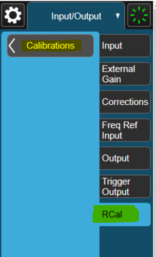
U9361 RCal calibrations are set up, performed and applied on the X-Series signal analyzer using the Calibration Configuration dialog, which is opened by clicking the Calibrations button on the RCal tab.
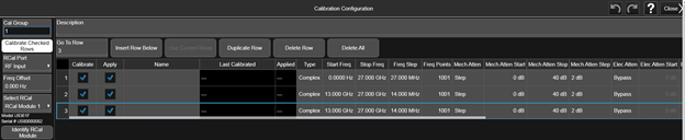
Each row of the table represents a correction at a specific instrument state. For a correction to be applied, the current instrument state must match the state of the instrument at the time the calibration was performed. As shown in the image above, there may be a database of existing calibrations to choose from. As long as the current instrument state matches one of these, calibration factors will be applied.
When the VSA software is configured to use an X-Series signal Analyzer, the Input Extensions dialogue, will display an RCal Correction parameter, which is used to enable or disable the corrections that are checked with "Apply" on the X-Series signal analyzer's Correction Configuration dialog.
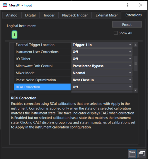
VSA does not perform U9361 RCal calibrations or select application of individual calibrations. That is done on the X-Series signal analyzer's Correction Configuration dialog. The VSA software enables or disables en masse all calibrations marked for application on this dialog.
For calibration correction to be applied, a calibration must be selected for Apply on the xSA Calibration Configuration dialog, enabled by the VSA input extension RCal Correction, and the instrument state set by VSA must match the instrument state of at least one applied correction in the xSA Calibration Configuration. If the VSA state does not match any of the enabled corrections then no corrections are applied, even though RCal Correction is Enabled. The CAL? Trace indicator is used to inform the user that no correction was applied even though it was enabled. The trace indicator is updated for each acquisition.
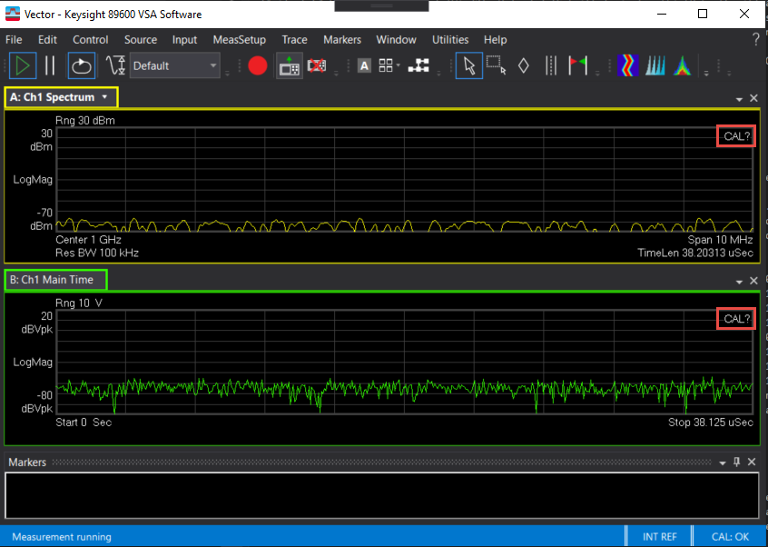
Clicking on the CAL? trace indicator opens a window that gives a brief description of the condition that caused the trace to be questionable.
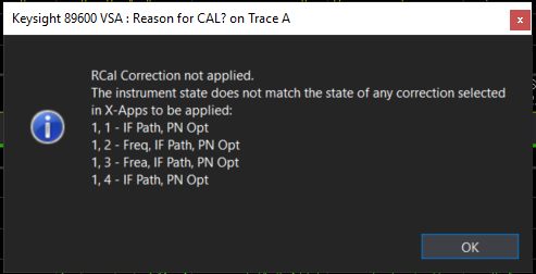
The description in the above message indicates that no correction was applied. The instrument state mismatches that disqualified each calibration are listed by group and row. If there are more than 16 calibrations, only the first 16 are annotated to ensure that it fits on the display of all instruments. If the description was truncated to the first 16 calibrations, ‘. . .’ is appended to the end. The CAL? trace indicator is not displayed if at least one of the enabled calibrations was applied for correction (e.g., the current instrument state matches the entire state of at least one calibration).
The following is a list of mismatches between acquisition state and calibration state that disqualify a calibration from being applied.
|
Mismatch |
Description |
|---|---|
|
Unknown |
An unknown calibration ID was requested for correction |
|
Cal Type |
Calibration type does not match |
|
Port |
The input port, set by External Mixer or input extension RF Input Port, does not match |
|
Freq |
Center frequency of acquisition does not match |
|
IF Path |
IF Path, set by Span and input extension Signal Path, does not match |
|
The Phase Noise Optimization, set by input extension Phase Noise Optimization, does not match |
|
|
Preamp |
The Preamplifier mode, set by Range and by input extension Preamplifier, does not match |
|
Preselector |
Preselector state, set by input extension Microwave Path control, does not match |
|
Coupling |
AC/DC coupling does not match |
|
Bypass |
Low band bypass state, set by input extension Microwave Path Control, does not match |
|
Mech Atten |
The mechanical attenuator value set by Range and by input extension Mechanical Attenuation, does not match |
|
Elec Atten |
The electronic attenuator value set by Range does not match |
|
Full Atten |
The second input attenuator value, set by Range and by input extension Mechanical Full Range Attenuation, does not match |
|
IF Gain |
The IF attenuator value, set by Range and by input extension IF Gain, does not match |
|
Mixing |
The image shift, set by input extension Mixer Mode, does not match |
|
Prefilter |
The prefilter setting does not match |
See Also
Available Measurement Hardware