Angle of Arrival (Pulse)
Menu Path:
The Analysis tab's Angle of Arrival panel lets you enable and configure Angle of Arrival analysis. The angle of arrival (AoA) of a signal is the direction from which the signal is received. To perform this measurement, you need at least 2 channels to calculate the angle.
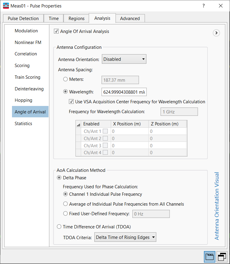
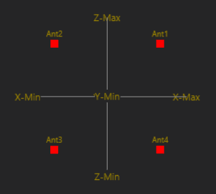
Antenna Orientation Visual -- Click the expand icon ![]() on the right side of the panel to show a
on the right side of the panel to show a ![]() 3D illustration of the current antenna configuration. See the Antenna Orientation description for additional antenna orientation diagrams.
3D illustration of the current antenna configuration. See the Antenna Orientation description for additional antenna orientation diagrams.
Right-click on the illustration to rotate the 3D visual around the origin.
The Angle of Arrival panel allows you to set the following parameters:
-
Angle of Arrival Analysis -- Enables or disables AoA analysis.
-
Antenna Configuration -- Contains a group of parameters used to define the antennas used in the AoA configuration.
-
Antenna Orientation: Selects up to four antennas alongside the physical orientation of the antennas. There is a one-to-one mapping between AoA channels and VSA measurement channels. The available choices depends on the number of input channels used in the measurement. Because AoA analysis requires at least two channels, the Antenna Orientation is Disabled by default because VSA starts up with only a single channel.
Channel orientation is important. With only two channels, we can only calculate either the elevation angle or the azimuth angle based on the two-channel orientation. For a horizontal orientation we can calculate the azimuth and for a two-channel vertical orientation we can calculate the elevation.
The Antenna Orientation selection will be visually represented in the Antenna Orientation Visual panel. The Antenna Orientation choices are also shown in the diagrams below (looking in the positive Y-axis direction, which we assume as boresight):
2 Ant Horizontal
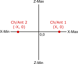
This enables azimuth measurements only.
2 Ant Vertical
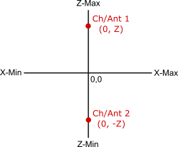
This enables elevation measurements only.
3 Ant L-Shaped
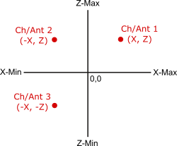
Azimuth would be calculated using channels 1 and 2 , and elevation would become calculated using channels 2 and 3.
3 Ant L-Shaped Flipped
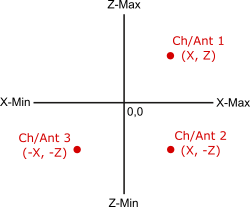
Azimuth would be calculated using channels 2 and 3, and elevation will be calculated using channels 1 and 2.
4 Ant Square
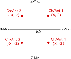
Default: Disabled
Choices: Disabled, 2 Ant. Horizontal, 2 Ant. Vertical, 3 Ant. L-Shaped, 3 Ant. L-Shaped Flipped, 4 Ant. Square
-
Antenna Spacing: Sets the physical spacing between antennas around the SUT (system under test). There are two ways to set the antenna spacing (either using meters or wavelength & the reference frequency).
-
Meters: Sets the antenna spacing in meters, mm or µm.
-
Wavelength: Sets the antenna spacing based on wavelength (λ, mλ or µλ) and frequency. The formula used for these calculations is c = λ f (c is the speed of light).
-
Use VSA Acquisition Center Frequency for Wavelength Calculation: When enabled, the VSA acquisition center frequency is used with the Wavelength setting to calculate wavelength-based antenna spacing. Frequency for Wavelength Calculation is grayed out when this setting is enabled.
-
Frequency for Wavelength Calculation: Enter a frequency to use with the Wavelength setting to calculate wavelength-based antenna spacing. This setting is only available when Use VSA Acquisition Center Frequency for Wavelength Calculation is disabled.
Wavelength, Use VSA Acquisition Center Frequency for Wavelength Calculation, and Frequency for Wavelength Calculation are convenience settings and are not saved to the setup file (File > Save > Save Setup).
-
-
-
Antenna Configuration Table: Shows the enabled antennas and their relative positioning on the X-Z plane.
-
Enabled: Displays the enabled antennas (channels). Use the Antenna Orientation parameter to select a configuration and enable antennas.
-
X Position (m): X-axis position in meters for each enabled antenna. Use the Antenna Spacing parameter to set the X and Y positions for all configured antennas.
-
Z Position (m): Y-axis position in meters for each enabled antenna. Use the Antenna Spacing parameter to set the X and Y positions for all configured antennas.
-
-
-
AoA Calculation Method -- Selects the AoA analysis mode.
- Delta Phase (default): Selects the Delta Phase AoA calculation method, which operates on the phase difference between channels to estimate angle. The differences must be less than 1 lambda for 'S = d * sin(angle)' because of the need to look at the difference in the same wave cycle for each channel. This analysis method can be used when the channels/antennas are closely spaced.
Delta Phase calculations are made using the following formula:
where k is the carrier freq, d is the distance between channels (antennas), delta is the delta phase between channels, and lambda is the speed of light.- Frequency Used for Phase Calculation: Selects the frequency value (and thereby the wavelength) to be used for AoA calculation. This parameter is valid when Analysis Method is set to Delta Phase.
- Channel 1 Individual Pulse Frequency: Uses the measured frequency mean of channel 1 on the Pulse Table.
- Average of Individual Pulse Frequencies from All Channels: Uses the measured frequency mean value of all valid channels.
- Fixed User-Defined Frequency: Enter a fixed user-specified frequency value (default = 0 Hz).
- Frequency Used for Phase Calculation: Selects the frequency value (and thereby the wavelength) to be used for AoA calculation. This parameter is valid when Analysis Method is set to Delta Phase.
- Time Difference of Arrival (TDOA): Selects TDOA as the AoA calculation method. TDOA detects the difference of timing at rising edges, falling edges, or center of rising and falling edges between the channels (specified by the TDOA Criteria parameter) as the reference timing. TDOA calculation method does not take into account channel phase differences, but rather only looks at the RF Radio Frequency: A generic term for radio-based technologies, operating between the Low Frequency range (30k Hz) and the Extra High Frequency range (300 GHz). amplitude envelope.
- TDOA Criteria: When TDOA is selected as the AoA calculation method, TDOA Criteria sets the point of reference for detecting the timing difference between channels.
Default: Delta Time of Rising Edges
Choices: Delta Time of Rising Edges, Delta Time of Falling Edges, Delta Time of Rising and Falling Edges
- TDOA Criteria: When TDOA is selected as the AoA calculation method, TDOA Criteria sets the point of reference for detecting the timing difference between channels.
- Delta Phase (default): Selects the Delta Phase AoA calculation method, which operates on the phase difference between channels to estimate angle. The differences must be less than 1 lambda for 'S = d * sin(angle)' because of the need to look at the difference in the same wave cycle for each channel. This analysis method can be used when the channels/antennas are closely spaced.
See Also
