FM Filter Bandwidth (Pulse)
Menu Path:
In order to trade off tracking movements in FM Frequency Modulation error against visualizing trends in a smooth trace, a trace filter is offered that enables you to set the amount of noise that will be included in you displayed trace. Setting this very, very low (e.g., 0.01%), and everything will look rounded and therefore inaccurate. If you set it too high (e.g., 50%), all of the noise in the span will be included in your trace, rendering the trace ineffective. The FM Filter Bandwidth specifies the 3 dB bandwidth for the low-pass differentiating filter applied to the Measured FM demodulation trace results. In this way, you can filter out unwanted signals and control the amount of noise included within the reported FM demodulation trace.
The FM filter is an ideal FM differentiating filter, combined with a variable-bandwidth low-pass filter. The low-pass filter is designed using a Kaiser window, which gives good flatness in the passband combined with very good rejection in the stop band.
You can set the Bandwidth Factor (%) value (valid range 0.05% to 50%) that is used to calculate the FM Filter Bandwidth (Hz) value as a percentage of the current measurement Span (Hz).
The determined FM filter bandwidth and time aperture are displayed below Bandwidth Factor, next to the labels Bandwidth and Aperture.
As an example, here is the FM Error Time trace with an FM Filter Bandwidth setting of 0.01%:
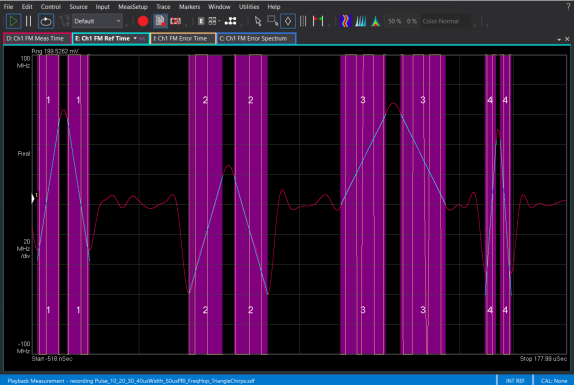
Here is the same trace with an FM Filter Bandwidth setting of 10%:

- Default value (Bandwidth Factor): 5 %