Common Pilot Error (802.11a/g/j/p OFDM)
When 802.11a/g/j/p OFDM Orthogonal Frequency Division Multiplexing: OFDM employs multiple overlapping radio frequency carriers, each operating at a carefully chosen frequency that is Orthogonal to the others, to produce a transmission scheme that supports higher bit rates due to parallel channel operation. OFDM is an alternative tranmission scheme to DSSS and FHSS. Demodulation is enabled, the trace data shows the difference between the measured and ideal pilot subcarrier symbols. The CPE error summary data provides the RMS level of the trace data as a percentage of the ideal signal (see CPE error summary data)
Residual phase and frequency settling that occurs following the preamble is measured via the display. With turned ON, this display shows the average phase error of the four OFDM pilots as a function of time (versus data symbol number). To convert to frequency units, select for the .
At each symbol-time in the burst, the measured symbol values of the four pilot subcarriers are compared with the ideal values. The differences are averaged together, producing a single complex value for each symbol-time. Normally the phase of this trace is displayed, showing how the pilot phase changes over the burst. The magnitude of this trace can be viewed to see signal magnitude changes over the burst.
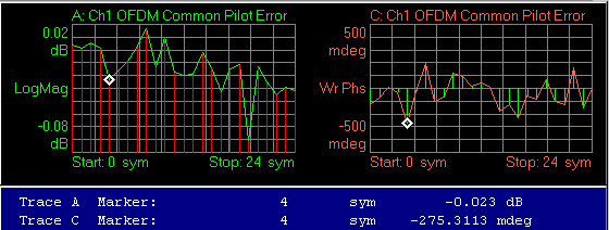
Demodulated IEEE Institute of Electrical and Electronics Engineers. A US-based membership organisation that includes engineers, scientists, and students in electronics and related fields. The IEEE developed the 802 series wired and wireless LAN standards. Visit the IEEE at http://www.ieee.org 802.11a/g burst with a result length of 25 symbols (0 through 24 sym). The left trace shows the magnitude error and the right trace shows the phase error.

OFDM Common Pilot Error
Symbol-time 4 Magnitude = -0.023 dB
Symbol-time 4 Phase = -275.3113 mdeg
See Also
