Balanced Measurements |
In this topic:
Standard Single-ended devices generally have one input port and one output port. Signals on the input and output ports are referenced to ground.

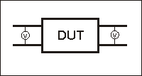
Balanced devices have two pins on either the input, the output, or both. The signal of interest is the difference and average of the two input or output lines, not referenced to ground. The two input or output lines are referred to as the 'logical' ports of the device.

Note: Because the FieldFox has only two RF ports, only balanced Reflection (NOT Transmission) measurements are possible.
On balanced devices, the signal of interest is the difference and average of the two input or output lines. In balanced device terminology, these signals are known as the Differential (difference) and Common (average) modes.
The following model shows how two signals (A and B) combine to create Differential and Common mode signals:
Signal A is fixed at 1V peak
Signal B is selectable
Differential is calculated as A minus B
Common is calculated as the AVERAGE of A and B
Note: Click Signal B selections to see various Differential and Common signals.
|
Signal A =1V |
|
|
|
|
|
|
Differential
|
Common (Avg)
|
|
|
|||
|
Signal B = SELECTABLE |
Calculations |
||
|
Single-ended0V |
1 - 0 = 1 |
(1 + 0)/2 = .5 |
|
|
180° Out of Phase.1V |
1 - (-1) = 2 |
(1 + (-1))/2 = 0 |
|
|
180° Out of Phase 2V |
1 - (-2) = 3 |
(1 + (-2))/2 = -.5 |
|
|
In Phase 1V |
1 - 1 = 0 |
(1 + 1)/2 = 1 |
|
|
In Phase 2V |
1 - 2 = -1 |
(1 + 2)/2 = 1.5 |
|
Note: The above model does not show a DUT. The difference and average of the two reflection signals are calculated for the FieldFox mixed-mode measurements.
The FieldFox does not provide true balanced measurements by stimulating both balanced inputs together and measuring both outputs relative to one another. Instead, the FieldFox makes only Single-ended measurements. It stimulates each input and measures each reflection individually. However, all measurements and calculations on the FieldFox are performed in frequency domain using complex (magnitude and phase) data. The Balanced S-parameter display data is then calculated from the measured data.
Mixed-mode S-parameters combine traditional S-parameter notation with balanced measurement terminology.
Some balanced devices are designed to amplify the differential component and reject the common component. This allows noise that is common to both inputs to be virtually eliminated from the output. For example, a balanced device may amplify the differential signal by a factor of 5, and attenuate the common signal by a factor of 5.
Using traditional S-parameter notation, an S11 is a ratio measurement of the reflection off the device Input divided by the stimulus at the device Input. Learn more about S-parameter notation.
The following explains mixed-mode S-parameter notation:
Sabxy
Where:
a - Logical FieldFox port from which the DUT is measured.
b - Logical FieldFox port from which the DUT is stimulated.
- Replace both a and b with one of the following:
d - differential (the difference between the two signals at the logical port)
c - common (the average of the two signals at the logical port)
x - Logical FieldFox port from which the DUT is measured (always 1 on the FieldFox).
y - Logical FieldFox port from which the DUT is stimulated (always 1 on the FieldFox).
Example
To view the difference between the reflections from the amplifier's two Inputs, divided by the difference between the two Input reference signals, we would select an Sdd11 measurement.
To make an Sdd22 measurement, connect the DUT output to the FieldFox ports .
Balanced measurements are calibrated in the same manner as single-ended (standard) measurements. For highest accuracy, a Full 2-port calibration is recommended.
Last Modified:
|
30-Jan-2014 |
New topic |