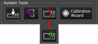
This topic describes the System Tools area. Click a region on the image to go to a description.
The System Tools manage the signal processing with the source and analyzer hardware.
Downloads all signals in the Signals resource panel to the selected source hardware, making them available for acquisition.
Auto Range Acquisition Input automatically sets the optimum full scale amplitude range for the input signal. You can use the Auto Range Acquisition Input button on the Signal Optimizer to quickly start an autorange. It samples the current input signal and then sets the full scale input range to the minimum range that includes the peak voltage sample of the input signal.
When the Signal Optimizer performs auto range, two changes are made to the measurement setup before measuring (sampling) the input signal:
Sets the auto-range measurement span to the maximum span possible for the current Hardware Configuration. This will include any out of band energy that is present in the input signal and at the input to the analog to digital converter.
Increases the measurement time. Longer measurement times increases the probability of capturing the peak voltage of narrow duty cycle pulsed input signals. The Search time is used for demodulation measurements on pulsed formatted signals.
Auto Range Acquisition Input may make more than one measurement to complete the process. If the first measurement detects an overload condition, the input range is increased and another measurement made. If the new autorange setting changes more than 15 dB then another measurement made to verify the new setting is correct.
In general, Auto Range is an estimate of an input range setting that will work, but will not provide optimal results. The specifics for finding the optimal input range setting vary depending on the hardware configuration type and measurement type, but in general follows the procedure below:
Auto Range Acquisition Input works well for most common input signals. Signals that don't work as well are:
Signals where the magnitude is slowly changing with respect to measurement span.
Pulsed signals with a duty cycle smaller than 10%.
For Signals where the measurement span is significantly less than the maximum span of the hardware, Auto-range will attempt to make a full span measurement. This full span measurement could be limited by the number of measurement points necessary to complete the measurement resulting in a very slow auto-range cycle. If the number of points becomes too large, the auto-range measurement will be scaled back to perform the analysis in the measurement span rather than the full span of the hardware. This could cause the peak of the signal to be missed if there is out of band energy in the signal. Change to a span wide enough to capture the out of band energy and then perform the auto-range.
Some models of the oscilloscopes (those with very high maximum sample rates) are vulnerable to the measurement span issue mentioned above. Also, the Zoom property in oscilloscopes can include image related energy in the measurement that will cause auto-range to end up on a range too high.
For the Z9070B hardware configuration, the auto-range function does not work and results in an input range setting that may be off by as much as 20 dB. It is recommended to use a manual approach for choosing input range setting when using a Z9070B hardware configuration.
The input signal to the analyzer hardware is currently disconnected. Click this button to connect it.
The input signal to the analyzer hardware is currently connected. Click this button to disconnect it.
Opens the Calibration Wizard Setup window where you can begin configuring both single-point and multi-point system calibrations. Refer to the Calibration Wizard topic to learn more.