The following are considerations when setting up and performing a GRL cal.
Choose antennas that will produce approximately a TEM wavefront at the surface of the sample. The size of the sample and metal plate needs to be large enough include the energy being radiated by the antennas.
This is important because time domain is used to isolate the reflections off each of the two antennas. Because of this, aliasing must be considered. Learn more about Aliasing. (Internet connection required.) The alias free range can be calculated as shown.
Range = (number of points-1)/ (stop frequency - start frequency)
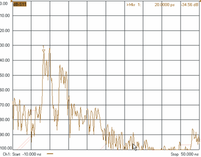
It is important that the alias free range be greater than the length of the freespace fixture. This includes all paths until the signal is attenuated to an insignificant level. Below is an image of S11 of the empty fixture with a calibration coaxial/waveguide calibration turned on.
Note: Beginning with E.07.02 you can change the number of points after calibrating. The original calibration can be reused with interpolation ON.

This measurement was made with a calibration performed at the end of the cables connected to the antennas. Note that the reflections before time equal zero are small. For a perfect calibration without any measurement noise the reflection would be zero (minus infinity dB).
If you are performing a ‘Perform a one-tier gated reflect line calibration (GRL) ...’ calibration, the time where the reflections are zero will occur in negative time. The following image shows this:
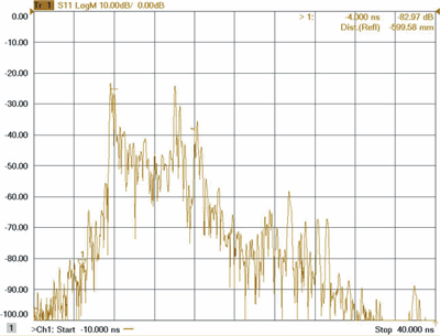
Note that all the reflections below approximately -4 nsec are insignificant (below -80 dB). This is the value that you would enter as the ‘Test Set Start Time’ when ‘Perform a one-tier gated reflect line calibration (GRL) ...’ is selected. This value should be verified for both forward and reverse measurements (S11 and S22).
In the following image, the first series of reflections, after t=0, is the reflections associated with the antenna. Next we see the reflections off the receiving antenna and the supporting structure. The response then reduces to approximately zero at about 20 nsec. Since the measurement was made over x-band (8.2-12.4 GHz) the minimum number of points can be calculated as:
Number of points = 1 + Range*(stop frequency - start frequency)=1 + 20e-9*(12.4 e9 - 8.2 e9) = 85
Based on the required range the minimum number of points required is 85. In general the more points the better to insure that as little aliasing occurs as possible. The same analysis should be performed on S21.
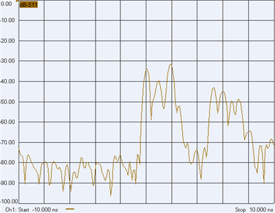
The next step is choosing the time domain parameters. The start and stop times are used to locate the position of the metal plate and the length of the fixture. This is the same for both types of GRL calibrations. Below is a plot of the empty fixture.
and the fixture with the metal plate.
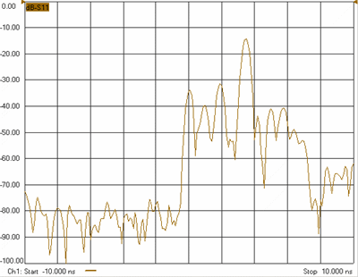
By comparing the two plots, the time position of the plate fall between 2 and 6 nsec. The exact position is not important as long as you specify times where no other reflection has larger amplitude than the reflection off the plate. This can occur when the reflection off the antenna is larger than the plate.
These parameters are used during the gated response isolation portion of the calibration. This calibration is separate from the GRL cal and is used to reduce any residual errors. The gate span should be set wide enough to include the entire response of the reflection off the plate or the transmission of the empty fixture but narrow enough to minimize the unwanted responses. Below is a plot of the transmission response of the empty fixture.
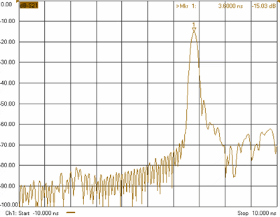
For this measurement a 1 nsec gate span is wide enough.
Ideally the metal plate should be approximately as thick as the sample to be measured. This puts the measurement reference planes at the surface of the sample. While this is ideal, any thickness differences are accounted mathematically by the sample holder description entries. The metal plate used in the example freespace measurement was .02 inches and the sample thickness was .1 inch. This is not optimum but appears to work well.
The size of the sample and the distance the sample needs to be from the antenna can be determined by analyzing your fixture using time domain. The minimum sample size is determined by the antennas used. First locate the position of the metal plate in time. When the plate is removed, the difference in the response should be large. You should not be able to see the fixture's supporting structure. At least 50 dB. The greater the better. The fixture opening used in the sample measurement was 18'x18".
The distance from the antenna to the sample can be determined by looking at the time domain response of the metal plate measurement. These should be a low reflection span of time between the last response of the antenna and the metal plate. The physical distance used in the sample measurement was 11".