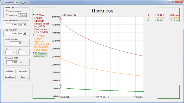
This feature provides you with the suggested thickness of the sample (also known as sample length) given the Coax or Waveguide dimensions and operating frequencies.
With Opt. 001 Transmission Line and Free Space Method selected from the Measurement Launcher:
Click Measure, then Sample Thickness.
Y-axis units for the plot are in Meters /millimeters.
The Maroon trace plots the half-wavelength values. The NIST and 'FAST' models suggest that the sample thickness be at least a half-wavelength.
The Gold trace plots the quarter-wavelength values. The Nicholason Ross (NR) and Polynomial fit models suggest that the sample thickness be at least a quarter wavelength..
The Green trace plots the 20 degree minimum values. This is the minimum sample thickness needed to make an adequate measurement.
Fixture Type: Choose from: Coax or Waveguide.
Click Find to start the Waveguide finder dialog (below).
Start / Stop Frequency - Sets the frequency range over which the suggested sample thickness will be plotted.
Number of points - Sets the resolution of the plotted data traces.
~εr - approximate permittivity of the sample.
~µr - approximate permeability of the sample.
Waveguide Width - Width dimension of waveguide. This value is returned automatically for bands that are listed from the waveguide finder.
Calculate - Click to plot the half and quarter wavelength suggested sample thickness.
Autoscales - automatically scales the plot.
Reset Scale- returns the scale to the original values.
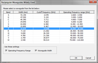
Select a banded waveguide.
Then check Operating Frequency range and/or Waveguide Width to populate the previous dialog with these values.
Press OK.