The N1500 Opt.003 Software and a 85072A 10 GHz Split Cylinder Resonator provides a complete turn-key solution for the IPC test method TM-650 2.5.5.13 , Permittivity and Loss Tangent Using a Split-Cylinder Resonator.
The 85072 Resonator. Refer to the Technical Overview of the 85072A for details.
When Resonant Cavity Methods (Opt. 003) is selected from the Measurement Launcher, the following dialog appears:
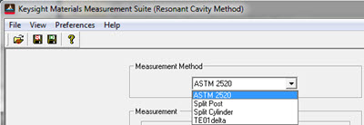
Select Split Cylinder.
The following dialog box appears:

The split cylinder method calculates the permittivity of the material sample by measuring the closed cylinder and the cylinder opened with a sheet of material inserted between the cylinder halves. There are many responses available over the usable frequency range of the 85072A but only the TE0nm modes can be used to calculate the permittivity using the IPC test method TM-650 2.5.5.13.
To insure that the measurements are made at the correct frequency, an estimate of the real part of the permittivity (dielectric constant) is required. This estimate can be entered manually if the approximate value of the dielectric constant is known. If not, the estimate can be determined by measuring the TE111 mode. Measuring dielectric constant using this mode is not as accurate it is accurate enough to provide an estimate when using the IPC test method TM-650 2.5.5.13. The advantage of using this mode for an estimate is that it is always the first resonant mode for the 85072A. Even if you have knowledge of the material it is recommended that the estimate be measured by clicking the Measure button.
The Measurement Frequency selection box shows the first ten TE0nm frequencies based on the entered sample thickness and the value of the estimated dielectric constant, er. The default measurement frequency is the TE011 frequency. When any other frequency is selected, the analyzer is set to that frequency and the indicated frequency span. Since it is possible for other non-desired resonant modes to occur near or at the selected frequency, it is recommended that you observe the measurement on the analyzer display.

If the response is distorted by an adjacent response, you can either pick a different measurement frequency or change the thickness of the sample. One way of changing the sample thickness is to stack two samples together.
The Split Cylinder measurement method may prompt you to adjust the 85072A’s coupling. See the 85072A’s operating manual for how to perform this task.
![]()
The sample information is displayed next to the Set Range button.
Depending on the measurement method selected this area will change appearance.
Insert the sample, then click Measure to trigger a measurement of the cavity’s resonant frequency and Q.
The split cylinder measurement method sometimes requires an adjustment of the 85072A’s coupling. See the 85072A’s operating manual for how to perform this task.

After the measurement the results will be displayed.
Calculated er'’
This is the calculated value of the dielectric constant. When the split cylinder method is selected an estimate of the associated measurement error will be displayed. These errors are based on various measurement errors.
Calculated er'’’
This is the calculated value of the loss factor. When the split cylinder method is selected an estimate of the associated measurement error will be displayed. These errors are based on various measurement errors.
Loss tangent
This is the calculated value of the loss tangent (e”/e’). When the split cylinder method is selected an estimate of the associated measurement error will be displayed. These errors are based on various measurement errors.
Split cylinder method ONLY. This is the recommended method for making the first measurement of an unknown measurement. When this button is clicked the following property page will appear.

Enter the sample thickness and review the current values of the closed cylinder’s resonant frequency and Q. If desired, or if it has not been measured, click on the Measure button. When satisfied click on the Next button. This triggers the measurement of the TE111 mode response used to estimate the dielectric constant of the material. See the Set range topic above for more details. When complete, the property page below will appear. It shows the measured estimate and the other measurement parameters.

The Advance Setup button displays the Set Range dialog box described above. When the Finished button is clicked a measurement will be triggered. The results will be displayed on the main dialog display.