See All Spectrum Analyzer Examples
Gated spectrum analyzer (SA) measurements (requires option 090) use triggering to capture data during the active trigger state only and thus ensure that the response more closely represents the device response. Learn more.
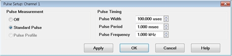
This example shows how to set up a gated SA measurement using an external or internal pulse to trigger the receiver measurement and an internal pulse to trigger the RF source. In order to pulse the PNA RF source with an internal pulse, option 025 is required. This option is not required in the case of an external RF source with pulsed capabilities.
Note: Internal Pulse0 pulse generator is not suitable for gated SA because the pulse width cannot be set. Instead, use Pulse3 as shown in this topic (pulse 1 to pulse 4 would work too, but without the direct Trigger source to Pulse3 internal connection).
Many of the setup steps can be performed automatically if option 008 is installed. The quick setup will configure a gated SA measurement using internal pulse generators and modulators. The RBW will be set to the maximum setting that is compatible with the pulse width. If minor adjustments are required after performing the quick setup, refer to the Complete Measurement Setup.
Select Spectrum Analyzer, then either:
OK delete the existing measurement, or
New Channel to create the measurement in a new channel.
Select Spectrum Analyzer, then either:
OK delete the existing measurement, or
New Channel to create the measurement in a new channel.
Selecting High Level (or Low Level) under Level/Edge triggers LO acquisitions and continues to acquire data while the pulse trigger remains high (or low).
Note: Edge triggering does not perform gated measurements.
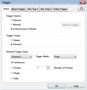
For gated SA measurements, Point does not refer to a data point or display point. Instead, it refers to the next LO acquisition. For SA, each time the LO is shifted an acquisition is captured. The time for each LO acquisition is based on the ADC Record Size times the ADC Sampling Frequency (10 nsec). The number of LO acquisitions is determined by the Image Reject setting. This information is displayed in the SA Setup dialog in the Advanced tab.
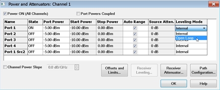
Open Loop leveling is used during pulse conditions with the internal source modulator. No leveling is used in setting the source power. Learn more.