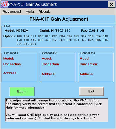
This adjustment sets the IF attenuator/gain stages to present a relatively consistent level to the ADC versus frequency for a given amount of signal. This maximizes the dynamic range of the instrument by preventing any IF compression at higher levels. The adjustment range is about 18dB with one adjustment value per band per input: R1, R2, R3, R4, A, B, C, and D (if applicable.)
The program first finds the peak of each band’s frequency response with a fixed input level. It then re-measures those peaks with a power meter. From this information, it determines the optimum gain or attenuation needed to keep all bands as similar as possible for any given frequency.
IF Gain Adjustment should be performed when any of the following occur:
An assembly in the reference receiver path (R1,R2) is replaced.
The Test Set Motherboard is replaced
The IF Mux assembly or SPAM assembly is replaced
Power Meter and Sensor(s) - These must cover the full frequency range of the PNA.
GPIB cable, LAN, or USB cable depending upon the type of Power Meter/Sensor being used.
Adapters as needed
Note: You must be logged onto the PNA as an Administrator to perform an adjustment. Learn more.
Click Utilities, then System, then Service, then Adjustments
At the Adjustments selection, click IF Gain Adjustment.

Note: Connect the Power Meter/Sensor to the PNA USB, GPIB, or LAN input depending on the type of Power Meter/Sensor being used. The program will prompt you where and when to attach the RF input for the Power Sensor(s).
Ensure the Reference Channel paths are properly configured and the connections are properly torqued.
Click Begin
Follow the instructions displayed in the program.
The adjustment takes about 5 minutes to complete for a 26.5 GHz PNA. Higher frequency units may take longer.
The Default menu selection (under the advanced menu) is for factory personnel only. This will preset all values to default levels for trouble shooting purposes only. If this is selected, a full IF gain adjustment will need to be performed.
The correction data is stored in the flash memory on the Test Set Mother Board.
Last modified:
|
10-Dec-2013 |
Connection edits per JV |
|
20-May-2013 |
Updated per JV |
|
3/7/07 |
Added N5242x information. |