
The Digital Predistortion (DPD) feature in the VNA characterizes and then creates a model of the non-linear distortions of power amplifiers caused when operating in the amplifier's compression region. DPD then creates a DPD waveform (inverse distortion) so that the DUT output will approximate the desired ideal waveform. DPD provides improved linearity to allow transmission of signals at lower distortion levels.
Note: Digital Predistortion is a Licensed Feature. Learn more about Licensed Features.
In this topic:
Creates DPD model
Validates DPD model (evaluate improvement that is possible using particular model)
Measures spectral regrowth (quantified as ACPR)
Measures in-band distortion (quantified as EVM or NPR)
Modulation Distortion Option S93070xB
Requires a configurable test set (it does not work with N522xB-200/210/400/410)
2-Port or 4-Port E5081A VNA
M983xA PXIe VNA (single module)
Supported external sources:
M8190A with E8267D PSG Vector Signal Generator
M9383A/B, M9384B (wideband vector, 44 GHz, with enhanced phase noise)
N5182B MXG RF Vector Signal Generator
N5192A and N5194A UXG Vector Adapter
Note: When setting up an M9383A, M9383B, or M9384B source in the External Device Configuration dialog, select MXG_Vector as the driver (they are code compatible).
Windows 10 operating system
The diagram shows the signal flow and waveforms through the VNA to the DUT input and output.

|
Waveform |
Description |
|
Ideal |
This is the desired Ideal waveform, which is the default modulation file currently selected in the Modulate tab of the Modulation Distortion Setup dialog. |
|
Ideal DPD |
The model is applied to the Ideal waveform to create the Ideal DPD waveform. This waveform does not have source correction applied. |
|
Corrected DPD |
Ideal DPD waveform with source correction applied. |
|
~Ideal DPD |
DUT input signal with DPD and source correction applied. This approximates the Ideal DPD waveform. |
|
~Ideal |
The DUT output signal with DPD and source correction applied. This approximates the Ideal waveform. Most of the distortion from the DUT is tuned out of the signal at this point. |
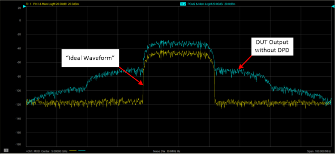
The following example shows a typical Ideal Waveform and DUT Output without DPD applied.
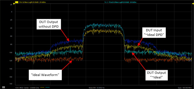
After applying DPD, the following shows typical ~Ideal DPD and ~Ideal waveforms.
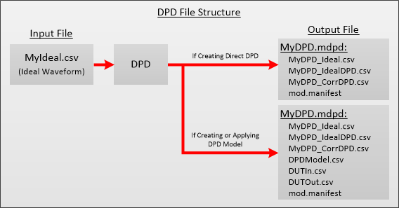
The following table describes the files in the DPD file structure:
|
Filename |
File Description |
|
MyDPD_Ideal.csv |
This is the original Ideal Waveform. |
|
MyDPD_IdealDPD.csv |
Ideal DPD waveform without source correction applied. |
|
MyDPD_CorrDPD.csv |
Ideal DPD waveform with source correction applied. |
|
DUTIn.csv |
Waveform measured at the DUT input which is used to create the DPD Model. |
|
DUTOut.csv |
Waveform measured at the DUT output which is used to create the DPD Model. |
|
DUTLinearGain.csv |
Contains the linear gain of the DUT if the DPD model is Dynamic Gain. |
|
mod.manifest |
File containing setup information. |
|
DPDModel.csv |
Contains the DPD model parameters. |
Direct DPD determines the maximum possible improvement to in-band EVM. This method generates a predistorted signal and does not use a model.
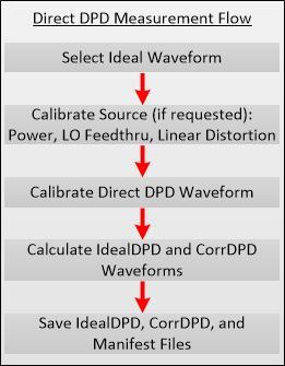
The following diagram shows the measurement flow for modeling.
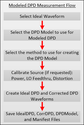
Memory Polynomial Modeling is a technique that uses a memory polynomial algorithm to create the model. This model depends on past and future input values to account for memory effects. The past/future input values define the number of input past/future time samples to use for calculating the current output sample.
Note: Dynamic Gain of measurements above 50 GHz requires the S93110B Active Hot Parameters license
Dynamic Gain Modelling is a technique that uses dynamic gain algorithm to create the model. The gain is characterized by the AM-AM (magnitude ) and AM-PM ( phase) functions, which are associated with the memory operators. There are a total of four memory operators that users can choose from to include in the gain algorithm.