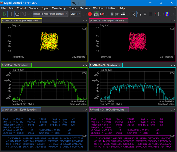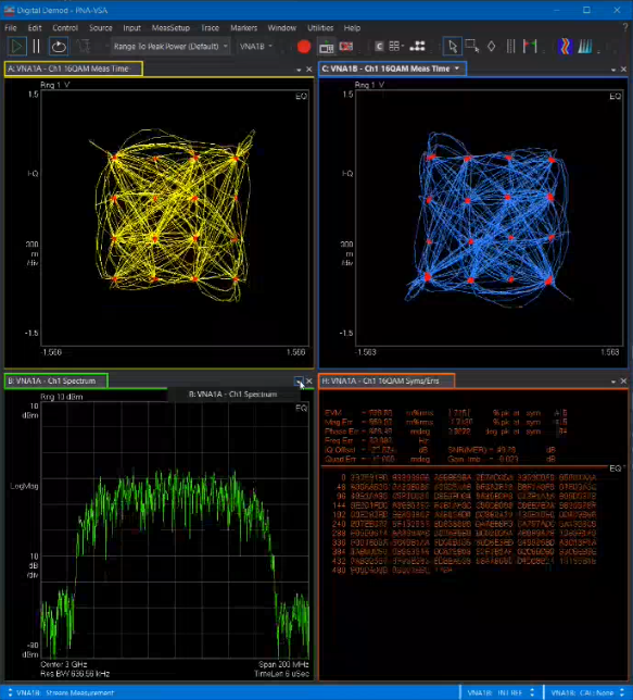
Connecting the VNA to the VSA 89600 software allows for greater signal evaluation and troubleshooting. Perform dynamic compression with modulated signals, characterize linearization techniques of modulated signals on amplifiers, verify modulated performance, and demodulate and analyze complex signals.

Note: IQ data output is a Licensed Feature. Learn more about Licensed Features.
In this topic:
Minimum VSA license 89601200C, minimum VSA release 2022_Update_1.0, Build 26.20.233
VNA Option S93090x Spectrum Analyzer or Option S93070x Modulation Distortion
Up to date support contract on either the SA or MOD distortion license
VNA Option S93050B Vector Signal Analyzer (1.5 GHz span required if span exceeds 200 MHz)
2-Port or 4-Port VNA
M983xA (PXIe VNA)- single module only
VNA Option S95050B Vector Signal Analyzer (1.5 GHz span required if span exceeds 200 MHz) or
VNA Option S95051B Vector Signal Analyzer (4 GHz span required if span exceeds 200 MHz)
E5081A (2-Port or 4-Port VNA)
VNA Option S96050B Vector Signal Analyzer (1.5 GHz span required if span exceeds 200 MHz) or
VNA Option S96051B Vector Signal Analyzer (4 GHz span required if span exceeds 200 MHz)
Windows 10 (64 bit) operating system
Minimum system CPU version 6.0, but later versions are highly recommended
Transfers only wave data (a1, b2, etc.) from VNA to VSA
Minimal control (VNA does not control the VSA and VSA does not control VNA)
SA must be in coherent mode (repetitive test signal)
PNA/E5081A configuration: VSA must be installed on the unit (will not work if VSA installed on an external PC)
PXI or Streamline VNA configuration: feature not available VSA and VNA applications must be installed on the same PC
Accessing VSA settings in SA channel |
|
Using Hardkey/SoftTab/Softkey |
Using a mouse |
Or
|
|
Accessing VSA settings in MOD or MODX channel |
|
Using Hardkey/SoftTab/Softkey |
Using a mouse |
Or
|
Or
|
|
Note: Settings in this dialog apply to the active channel only. VSA Setup dialog for SA channel
VSA Setup dialog for MOD/MODX channel
Connect VSA - Check to connect the VNA to the VSA and, if not currently running, start the VSA application automatically. Un-checking this checkbox will not close the VSA application but will disconnect the VSA from the VNA channel. Note: The connection to the VSA will only occur when the VNA is sweeping. If the VNA is on Hold mode, the VSA will not start or connect. Note: If the VSA was running before the connection occurs, the VNA connects to the running occurrence, and the VNA will not close VSA when quitting. If the VSA was not running before, VNA starts it when connecting, and will close it when quitting. Enable Digital Trigger - Check to make the exported data more stable from sweep-to-sweep. Un-checking this checbox makes the exported data less stable from sweep-to-sweep (starting time of the IQ recording is random). Saved State Includes VSA state ( all channels) - Check to automatically save the VSA state file and embed it into the VNA state file (.csa file). Stream Data to VSA - Check to stream data from the VNA to the VSA. Unchecking pauses data streaming but does not disconnect. Show VSA button - Moves the VSA window in front of the VNA GUI when the VSA-to-VNA connection is running. Autotune Spectrum button - Sets the VSA spectrum settings to match the current SA coherent repetition rate. In addition, it forces the VSA RBW to match the coherent tone spacing. VSA Status... button - Check to open the VSA Status dialog. Learn more. Select Data Receivers - (SA channels only) Stream trace data to VSA from selected receiver(s). PIn1 - Power In - (MOD/MODX channels only) Check to stream input power to a VSA measurement channel. VSA measurement channel numbers are assigned automatically in sequential order. POut2 - Power Out - (MOD/MODX channels only) Check to stream output power to a VSA measurement channel. VSA measurement channel numbers are assigned automatically in sequential order. PInWav - Ideal Waveform - (MOD/MODX channels only) Check to stream the Ideal Waveform input power to the VSA measurement channel. VSA measurement channel numbers are assigned automatically in sequential order.
|
|
|
|
|
|
Access the VSA LINK Status dialog by clicking on the VSA Status... button in the VSA Setup dialog. If the connection has been established, then the VNA LINK Status dialog displays a mapping between the VSA measurement channel and corresponding VNA channel/VNA measurement. VSA measurement channel numbers are assigned automatically in sequential order. Otherwise, it indicates “VSA not attached”. Displayed information in this dialog cannot be edited.
The text shown in the VSA Link Status dialog above represents configuration information from the VSA Channel Configuration pages (one page per VNA channel) in the VSA 89600 application. The following are the VSA Channel Configuration pages corresponding to the text above:
Example of VSA Channel Configuration page for VNA channel 1
Example of VSA Channel Configuration page for VNA channel 2
|
|
The following shows the VNA displaying the input and output of a mixer. Receiver a1 at Port 1 measures the input of the DUT and is a 3 GHz signal modulated by a QAM16 I/Q signal at the mixer input from the MXG. The LO is a 15 GHz signal from the internal Source 1 and output through Port 2. Receiver b4 at Port 4 is an 18 GHz signal at the mixer output. Using the VSA 89600 software, both the input and output signals of the mixer will be demodulated.
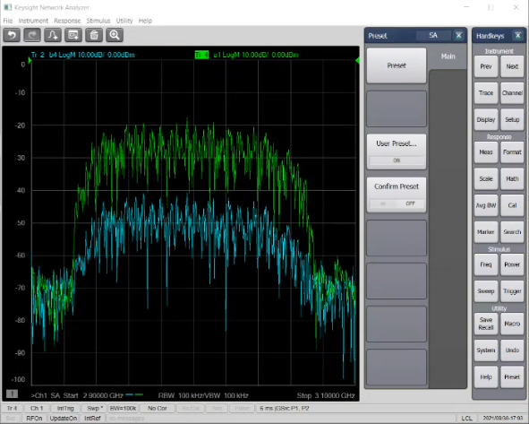
The following hardware setup was used in this example:
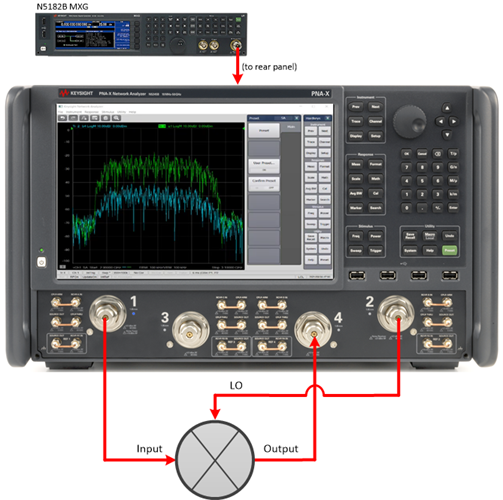
Note: The following procedure assumes that the VSA 89600 application is installed in the VNA.
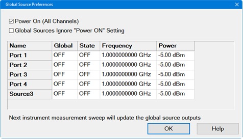
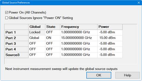
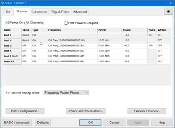
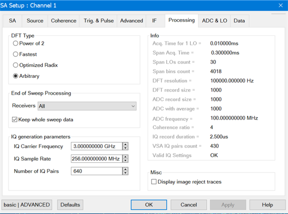
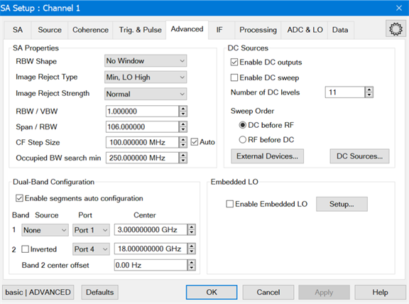
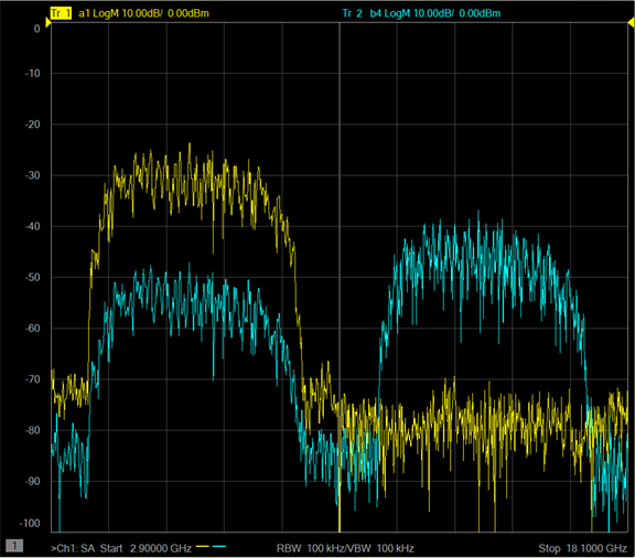
The VSA 89600 application will open automatically (may take 25 seconds).
When the link between the VNA and the VSA 89600 is established, the waveforms should be displayed in the VSA 89600 as follows:
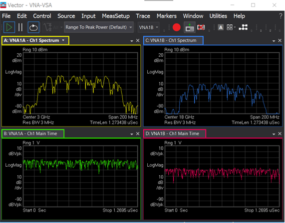
If the VSA window is behind the VNA GUI, press Math > VSA > Show VSA to bring the VSA window to the front.
