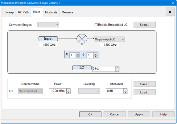
For purposes of these examples, only 1 converter stage will be configured.
If the Modulation
Distortion Setup dialog is not displayed, press Freq>
SA Frequency > MOD
Setup....
The Sweep,
RF Path, Mixer, Modulate,
or Measure tab
functions can now be selected.
Select the Mixer
tab.

In the Converter
Stages pull down menu, select 1.
Click on the Source
Name pull down menu then select
Port 3. This is the LO source.
Adjust the Power
using the up/down arrows or by double-clicking in the data entry field
and entering the value using the displayed keypad.
Click on the Leveling
pull down menu then select Open Loop
or Internal. The Open
Loop selection does not use ALC or receiver leveling. The Internal selection uses ALC leveling.
Adjust the receiver Attenuator
using the up/down arrows or by double-clicking in the data
entry field and entering the value using the displayed keypad.
Adjust the LO frequency using the up/down arrows or by
double-clicking in the data entry field and entering the frequency
using the displayed keypad.
Set the multiplier and denominator. The combination
of numerator / denominator forms a fractional value that is multiplied
by the input and LO frequency ranges. Learn
more.
Adjust the Input
using the up/down arrows or by double-clicking in the data
entry field and entering the frequency using the displayed keypad.
This is the same as Carrier Freq
In in the Sweep tab.
Click on the Output equation pull down menu then select
the mixer configuration calculated from the output mixer equation
selection.
To save the
mixer setup, click on the Save...
button then enter the file name and directory path.
If the Modulation
Distortion Setup dialog is not displayed, press Freq>
SA Frequency > MOD
Setup....
The Sweep,
RF Path, Mixer, Modulate,
or Measure tab
functions can now be selected.
Select the Mixer
tab.

In the Converter
Stages pull down menu, select 1.
Adjust the LO frequency using the up/down arrows or by
double-clicking in the data entry field and entering the frequency
using the displayed keypad.
Set the multiplier and denominator. The combination
of numerator / denominator forms a fractional value that is multiplied
by the input and LO frequency ranges. Learn
more.
Adjust the Input
using the up/down arrows or by double-clicking in the data
entry field and entering the frequency using the displayed keypad.
This is the same as Carrier Freq
In in the Sweep tab.
Click on the Output equation pull down menu then select
the mixer configuration calculated from the output mixer equation
selection.
Click on the
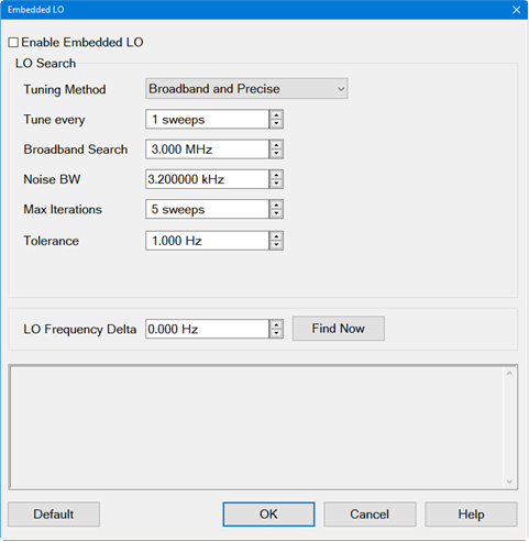
Setup... button. The Embedded LO dialog is displayed:

Check the Enable Embedded LO check box.
Click on the Tuning Method pull down menu. These
settings determine the amount of time spent versus the degree of accuracy
to which the LO Frequency is measured. Accuracy is compromised
when noise starts to appear on the measurement trace. Select
from the following:
Broadband and Precise
Does the entire tuning process for each background sweep.
Precise Only
Does NOT perform broadband tuning on each sweep. Use this
setting when the embedded LO is stable. The signal (after broadband)
must be within ½ the tuning IFBW. If the signal will always
be within ½ the IFBW, broadband tuning is not needed.
Disable Tuning
Only the previously measured LO
Frequency Delta is applied to the reference mixer LO and
VNA receivers.
Set the Tune every interval at which tuning
is performed before a measurement sweep using the up/down arrows or
by double-clicking in the data entry field and entering the value
using the displayed keypad. For example, 'Tune every 3 sweeps' means
that every third measurement sweep is preceded by tuning sweeps. If
the embedded LO drifts, or if regularly changing DUTs, set it to 'Tune
every 1 sweep'.
Set the Broadband Search frequency span
over which to measure the embedded LO frequency using the up/down
arrows or by double-clicking in the data entry field and entering
the value using the displayed keypad.
Set the Noise BW used for Broadband and
Precise tuning sweeps using the up/down arrows or by double-clicking
in the data entry field and entering the value using the displayed
keypad. This sets the resolution in the Broadband sweeps.
Set the Max Iterations of Precise sweeps
to make using the up/down arrows or by double-clicking in the data
entry field and entering the value using the displayed keypad. When
this number is reached, the final measurement is used.
Set the Tolerance using the up/down arrows
or by double-clicking in the data entry field and entering the value
using the displayed keypad. When two consecutive Precise measurements
are made within this value, the final measurement is used. If this
is not achieved within the Max Iterations value, then the last measurement
is used.
Click on the
Find Now button to find and
measure the actual LO frequency using the current dialog settings.
This data is displayed in the Status box.
The LO Frequency Delta displays the
absolute difference between the measured embedded LO frequency and
the LO setting that is entered in the Mixer Tab dialog.
Click on the
OK button.
In the Mixer tab, click on the Apply
button to apply the settings.
To save the
mixer setup, click on the Save...
button then enter the file name and directory path.

