Millimeter Configuration

This topic describes the Millimeter Configuration dialog functions used to configure the N5290A/91A for broadband or banded measurements.

In this topic:

See Also

Accessing Millimeter Configuration Dialog

Broadband Millimeter Configuration Dialog

Broadband Millimeter Configuration dialog box help

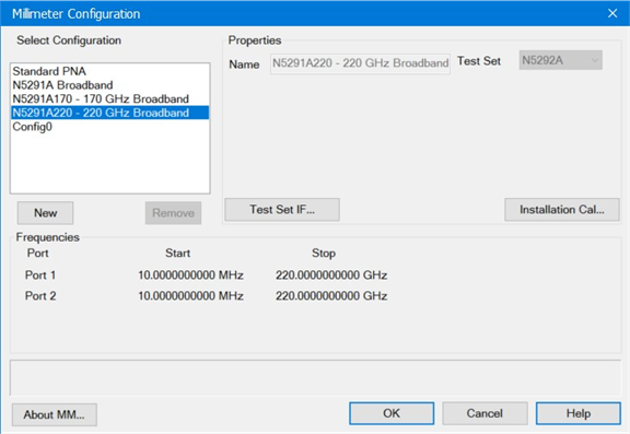
Select Configuration  Lists the Standard VNA configuration, N529xA configuration, and other configurations that you have created.

  • Click New to create a new Millimeter Module configuration. A name is automatically selected. Edit the Selected Configuration field to change the configuration name.

  • Click Remove to delete the selected Millimeter Module Configuration.

  • Select N5290A Broadband or N5291A Broadband

  • For banded, define a frequency band.

  • Select Standard PNA to exit the Millimeter mode to use the analyzer as a standard VNA.

Properties

Name  Shows the currently selected configuration. Edit this field to change the configuration name. Type a unique name using only alphanumeric and underscore characters.

Test Set  When N5290A Broadband or N5291A Broadband is the selected configuration, the N5292A test set is automatically selected. No other test set can be selected for the Broadband configuration.

Enable Modules  Enable or disable modules (frequency extenders) for the corresponding ports.

Test Set IF... button
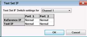
Test Set IF Switch settings for Channel N  Route the Reference or Test IF to the front panel (Front) or rear panel (Normal) of the test set. The Normal setting sets the IF bandwidth to 40 MHz. The Front setting sets the IF bandwidth to 2 GHz. Each port has a Reference IF and a Test IF switch. Each IF switch is independent per port and per channel. At preset, the default is Normal. IF switch settings are saved with the instrument state.

Installation Cal...  The installation calibration adjusts the source power at the output of the N5293A or N5295A Frequency Extender. It also adjusts for IF path loss variation. These can change each time a frequency extender is moved from one port to another, or from one system to another. This calibration should be done each time a change is made to the configuration. For a procedure, refer to Installation Cal.

Frequencies

Port  This is the port number of the VNA when in Standard PNA mode or the port number of the N5292A test set when in N529xA Broadband mode.

Type  The port type is set to Module when a frequency extender (N5293A or N5295A) is detected at the port. The Enable Modules checkbox will be checked for the port. When a frequency extender is not detected at the port, or the Enable Modules for the port is deselected, VNA is displayed to specify the standard VNA operation at the port.

Start/Stop  Displays the Start and Stop frequency of the frequency extenders (N5293A or N5295A) connected to each port and/or any VNA port in standard mode. Start/stop frequencies can be set by pressing Freq > Main > Start or Stop then entering the frequency.

Cancel  Closes dialog box without saving changes.

OK  Saves the configuration and the VNA is Preset before making the appropriate settings.

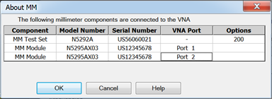
About MM...  Displays information about the current hardware configuration.
Banded Millimeter Configuration Dialog

Banded Millimeter Module Configuration dialog box help

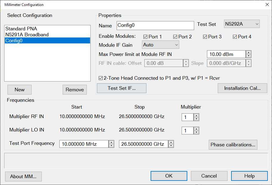
Select Configuration  Lists the Standard VNA configuration and other configurations that you have created.

  • Click New for first-time use.

  • For the N529xA, select N529xA Broadband.

  • For banded, define a frequency band.

  • Select Standard PNA to exit the Millimeter Configuration dialog.

Name  Shows the currently selected configuration. Edit this field to change the configuration name. Type a unique name using only alphanumeric characters and underscore.

New  Click to create a new Millimeter configuration. A name is automatically selected. Edit the Name field to change the configuration name.

Remove  Deletes a Millimeter Configuration.

Properties

Test Set  Select a test set to use in the current configuration. The firmware verifies that the selected test set is connected. If the selection does not match the connected test set, an error message is displayed. However, you are not prevented from continuing.

Enable Modules  Enable or disable modules (frequency extenders) for the corresponding ports.

Module IF Gain  When Auto is selected, the IF gain is automatically adjusted depending on the frequency of operation to avoid overdriving the receivers. In addition, you can manually select 0 dB, 2 dB, 4 dB, 6 dB, 8 dB, 10 dB, 11 dB, 13 dB, or 15 dB.

Max Power Limit at Module RF IN  The maximum mmWave module RF input is limited to this value when Test Set RF ALC is OFF. When you exit this dialog box using OK, set the power out of the VNA using the Power and Attenuator dialog.

Offset  Sets the loss of the cables. The mmWave module RF input is adjusted by this amount. Positive offset increases the power.

Slope  Helps compensate for cable and test fixture power losses at increased frequency. The mmWave module RF input power increases as the sweep frequency increases in dB/GHz. The slope is defined relative to the mmWave module RF input frequency. The slope starts at 0 Hz and a positive slope will increase the power level. Range is +/- 2 dB/GHz.

2-Tone Head Connected to P1 and P3, w/ P1 = Rcvr This checkbox is only available when using an N5292A test set and when Port 1 and Port 3 are checked in "Enable Modules."

Test Set IF... button

Test Set IF Switch settings for Channel N  Route the Reference or Test IF to the front panel (Front) or rear panel (Normal) of the test set. The Normal setting sets the IF bandwidth to 40 MHz. The Front setting sets the IF bandwidth to 2 GHz. Each port has a Reference IF and a Test IF switch. Each IF switch is independent per port and per channel. At preset, the default is Normal. IF switch settings are saved with the instrument state.

Installation Cal...  The installation calibration adjusts the source power at the output of the N5293A or N5295A Frequency Extender. It also adjusts for IF path loss variation. These can change each time a frequency extender is moved from one port to another, or from one system to another. This calibration should be done each time a change is made to the configuration. For a procedure, refer to Banded Installation Menu Calibration.

Frequency Settings

Multiplier RF IN  RF Frequency Range (displayed in grey fields) multiplied by the multiplier value equals test port frequency range.

Multiplier LO IN  LO Frequency Range (displayed in grey field) multiplied by this value equals the test port frequency. The IF frequency is:

  • PNA-X models = 7.438 MHz

Test Port Frequency  Set the Start and Stop frequencies of the selected configuration at the test ports. This becomes the displayed Start and Stop frequency of the VNA.

Important Notes

  • To set Test Port Frequency, first set the appropriate Multiplier values that are specified in your mmWave module documentation.

  • Ensure that the RF and LO Frequencies (highlighted below) are within the frequency range of the sources. The VNA offers no warning if they are NOT.

Source

Click a button to launch the External Devices dialog where you can select an internal or external source to be used for the VNA LO source or VNA RF source.

Cancel  Closes dialog box without saving changes.

OK  Saves the configuration and the VNA is Preset before making the appropriate settings.

About MM...  Displays information about the current hardware configuration.

Warning Messages

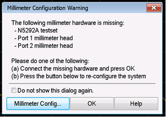
The following dialog indicates that an N529xA Broadband configuration is active but some hardware is missing. It will only list the hardware that was not detected. In this case the test set and two selected heads were not found. The Do not show this dialog again check will suppress this dialog until the firmware is restarted.

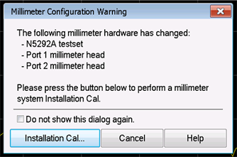
This following dialog indicates that an N529xA Broadband configuration is active but some hardware is uncalibrated. It will only list the hardware that is uncalibrated but a full calibration should be executed if anything has changed. The Do not show this dialog again check will suppress this dialog until the firmware is restarted. For a calibration procedure, refer to Installation Cal.