Hot S22 Measurement
A 'Hot' S22 measurement is a normal S22 measurement of a power amplifier
with drive power applied to the amplifier input. This situation more closely
resembles the output match characteristics of an amplifier under normal
operating conditions.
Note: Refer also
to Active (Hot) Parameters
for the latest Hot S22 measurement technique.
Procedure
On the PNA-X:
Press Meas >
S-Param > Meas
Class..., select Standard,
then click OK.
Press Meas >
S-Param > S22.
Press Freq,
then set the Start and Stop frequencies for the measurement.
Press Freq >
Main > Frequency
Offset.... Enable Frequency
Offset and set the Source(2) frequencies with a positive or
negative offset of at least (100 * IFBW). This will be the Hot (Input)
signal and must be far enough away from the S-parameter frequencies
to avoid interference.
Press Sweep
> Sweep Timing > Sweep Mode to STEPPED.
Press Setup
> Internal Hardware >
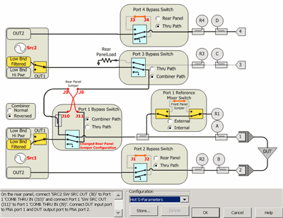
RF Path Config....

- For PNA-X models N5241B, N5242B, and N5249B: Under
Configuration select Hot S-Parameters. This is necessary
because these models have different path loss between J9 to Port1
and J10 to Port1 due to the bridge used as a combiner. The 'Hot'
(input) signal coming from Source 2 is routed through the coupled
arm of the combiner to port 1 and the DUT input. Configure the
rear-panel cables as shown in the above Path Configuration diagram:
On the rear panel, connect 'SRC2 SW SRC OUT (J8)'
to Port 1 'COMB THRU IN (J10)'
Connect Port 1 'SW SRC OUT (J11)' to Port 1 'COMB
THRU IN (J9)'.
Connect DUT input port to VNA port 1
Connect DUT output port to VNA port 2.
- For PNA-X models N5244B, N5245B, and N5247B: These
models use a splitter as a combiner. Set both the Port 1 and Port
3 Bypass Switch to Combiner
Path.
Press Power
> Main > Power
and Attenuators.... See Power
and Attenuator for more information.
For Port 2 (DUT output) select at least 10 dB
of source attenuation on the Source 1 path.
For Port 1 (DUT input) select the S-parameter
port power level.
Click Receiver
Attenuator.... Considering the gain of the DUT and the
Source 2 input power, select the appropriate attenuation for the
B receiver.
Perform a 2-port Calibration.
Press Power,
then Power and Attenuator,
and set Port 1 Src2 to ON.
Connect the DUT and measure S22. To ensure the DUT
is being driven and the desired power level, perform a Source Power
cal for Port 1 Src2.
In the Power and
Attenuators dialog, adjust the Port 1 Src 2 power level and
notice the change in S22.
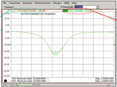
The following image shows a Hot S22 measurement of a Hittite HMC452ST89
Power Amp tuned for 900 MHz.

The Red circled measurement is Hot S22.
The other is with the Hot signal OFF.
If the Hot signal is too close to the measurement
signal, ripples appear on the out-of-band region of the trace.

