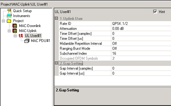
To access the UL burst editing window:

Expand MAC-Uplink
in the tree view and click
the UL User# you want to edit.
or
Click MAC-Uplink in the tree view to display all previously added bursts
in the right pane. Double-click in the first column of the burst that
you want to edit.
The UL burst editing window displays the UL burst parameters in the top pane and buttons for adding MAC PDUs (maximum eight) in the bottom pane.
Use this cell to select the burst modulation and coding rate type used for all MAC PDUs for this user (subscriber, SS, or CPE). The modulation types of the uplink user bursts do not have to be in any particular order.
Use this cell to set the relative power for each uplink user. Power can be attenuated by 0 dB to 40 dB to simulate bursts arriving from different users with different path losses. There must be at least one UL user burst with 0.0 dB attenuation to allow the signal generator to calibrate its power output.
Use this cell to set the relative time offset in integral units of the sample for the start of this user's burst. A zero value indicates that the burst starts exactly when scheduled. Offset values can be used to simulate time-of-arrival differences between different user transmissions. Setting the Time Offset [us] recalculates this value.
Use this cell to set the relative time offset for the start of the user's
burst. A zero value indicates that the burst starts exactly when scheduled.
Values ranging from
Use this cell to insert optional embedded midamble and postamble symbols in an uplink transmission. Midambles may be inserted every 4, 8, or 16 symbols with a postamble symbol at the end.
Use this cell to select the ranging burst mode on or off. Ranging allows the subscriber station to acquire the correct timing offset and power adjustments from the base station. Initial ranging allows the user to establish a link with a base station when it first starts up and to receive a CID assignment. Ranging bursts have a long preamble and are transmitted during the ranging interval time of the frame. User bursts have a short preamble and are transmitted after the request and bandwidth allocations.
Use this cell to select the subchannel index to be used. Refer to Table 213, OFDM Symbol Parameters, in the 802.16 specification, section 8.3.2 for the full definition of uplink subchannelization and use of specific subcarriers and pilot tones.
|
|
|
Use this cell to insert a transmission gap at the Physical layer after the user's transmission. This may be used to simulate a non-transmitting subscriber station. Setting the Gap Interval [us] recalculates this value. The minimum and default value is zero.
Use this cell to set a transmission gap in microseconds after the user's transmission. Setting the Gap interval [samples] recalculates this value rounded to an integer number of samples. The minimum and default value is zero.
Occupied OFDM Symbols
This cell tracks the number of symbols used in OFDM generation including preambles, midambles and postambles.
|
|
adds a MAC PDU to the selected burst. When you add MAC PDUs (maximum eight) to a burst, a data grid displays some of the parameters that you can edit by clicking each cell. To edit a full set of MAC PDU parameters, see Editing Tip. |
|
|
deletes a previously added MAC PDU. |
|
|
adds a MAC PDU that has the same configuration as the currently selected burst. |
|
|
swaps the currently selected burst with the one above it or the one just below it in the table for that link. |