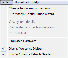
The System menu consists of the following menu items:

These menu items are used to configure the I/O (input/output) instrument interfaces and establish communication between the PC, signal generator, and spectrum/signal analyzer. Interface connections available include GPIB and LAN. You can also view the system details of the current hardware configuration, view the connection diagrams of supported systems, run an instrument self test, or change to a simulated hardware configuration.
The signal generator menu item uses the dialog window shown below for I/O configuration. The analyzer uses an identical dialog form for I/O connection.
This menu item starts the System Configuration Wizard at ![]() step 2,
where you select a specific system from a list of configured systems,
or configure a new hardware system.
step 2,
where you select a specific system from a list of configured systems,
or configure a new hardware system.
This menu item starts the System Configuration Wizard, where you configure
a new hardware system from a list of supported
configurations. You also access this from the Connect
to Instrument button  on the tool bar.
This menu item displays specific ![]() system details
of the currently selected hardware configuration, such as the name and
description of the system, instrument type, connection type (LAN or GPIB),
model and serial number, firmware revision and installed options.
system details
of the currently selected hardware configuration, such as the name and
description of the system, instrument type, connection type (LAN or GPIB),
model and serial number, firmware revision and installed options.
This menu item displays a ![]() connection
diagram
for the selected hardware system. See also Equipment
Setup.
connection
diagram
for the selected hardware system. See also Equipment
Setup.
Select this menu item to run an I/O interface connection test between
the hardware system and the PC. The ![]() Run Self-Tests
window appears and displays the results of the tests. If an error occurs,
a
Run Self-Tests
window appears and displays the results of the tests. If an error occurs,
a ![]() red X
appears next to the failed test and an error message is displayed in the
status area of the window.
red X
appears next to the failed test and an error message is displayed in the
status area of the window.
The N603xA/M933xA or N824xA memory is automatically erased after running Self Test.
Self Test does not support external upconversion or downconversion. The signal generator output should be connected directly to the analyzer input.
− Checks the I/O connection of the signal generator, verifies that the model number of the connected signal generator is supported, and validates that the firmware is compatible with the software version.
− Checks the I/O connection of the Arb, verifies that the model number of the target Arb is supported, and validates that the firmware is compatible with the software version.
− Checks the I/O connection of the spectrum/signal analyzer, verifies that the model number of the connected analyzer is supported, and verifies that the firmware is compatible with the software version.
− Verifies that the signal generator and arbitrary waveform generator I/Q ports are connected in preparation for performing a correction, verifies that the signal generator and analyzer RF ports are connected in preparation for performing a correction, and that a common 10 MHz reference is present.
This menu selection opens a dialog window where you select a ![]() simulated hardware system
from a list of supported configurations. These setups allow you to exercise
the user interface without having hardware connected to the PC.
simulated hardware system
from a list of supported configurations. These setups allow you to exercise
the user interface without having hardware connected to the PC.
This menu selection toggles on and off the opening ![]() welcome dialog screen.
This menu selection does not take place until the next time the N7620B
software is opened.
welcome dialog screen.
This menu selection does not take place until the next time the N7620B
software is opened.
When this setting is enabled (default is disabled), the ![]() Antenna Scan Refresh message is displayed when Antenna Type is not None and when the pattern item duration changes.
Antenna Scan Refresh message is displayed when Antenna Type is not None and when the pattern item duration changes.
The pattern item duration can change when: