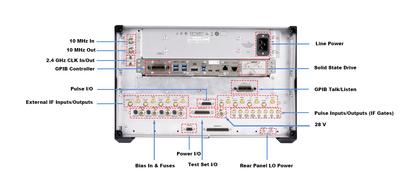
The NA520xA PNA-X Pro rear-panel layout is shown below. Click to view full-sized image.
See also:
External IF Inputs (Option D1F)
External IF Outputs (Option D1F)
|
Description |
Typical Performance |
|---|---|
|
Connector |
BNC, female |
|
Input frequency |
10 MHz ±0.3 ppm, 100 MHz ±0.3 ppm |
|
Input level |
10 MHz: -15 dBm to +20 dBm 100 MHz: -10 dBm to +20 dBm |
|
Input impedance |
50 Ω, nominal |
|
Description |
Typical Performance |
|---|---|
|
Connector |
BNC, female |
|
Output frequency |
10 MHz ±0.15 ppm, 100 MHz ±0.15 ppm |
|
Signal type |
Sine wave |
|
Output level |
+10 dBm ±4 dB into 50 Ω |
|
Output impedance |
50 Ω, nominal |
|
Harmonics |
<-40 dBc, typical |
|
Description |
Typical Performance |
|---|---|
|
Connector |
3.5 mm, female |
|
Input frequency |
2.4 GHz ± 0.3 ppm |
|
Input level |
-15 dBm to +20 dBm |
|
Input impedance |
50 Ω, nominal |
|
Description |
Typical Performance |
|---|---|
|
Connector |
3.5 mm, female |
|
Signal type |
Sine wave |
|
Output frequency |
2.4 GHz ± 0.15 ppm |
|
Output level |
+5 dBm ± 2 dB into 50 Ω |
|
Output impedance |
50 Ω, nominal |
|
Description |
Typical Performance |
|---|---|
|
Function |
Allows use of external IF signals from remote mixers, bypassing the PNA's first converters |
|
Connectors |
SMA (female); A, B, C, D, R1, R2, R3, R4 (4-port); A, B, R1, R2 (2-port) |
|
Input impedance |
50 Ω |
|
RF damage level |
+23 dBm |
|
DC damage level |
1 VDC |
|
0.1 dB Compression point (Normal IF path) |
-1.02 dBm at 7.365 MHz |
|
Description |
Typical Performance |
|---|---|
|
Function |
Allows use of external IF signals from internal mixers |
|
Connectors |
SMA (female); A, B, C, D, R1, R2, R3, R4 (4-port); A, B, R1, R2 (2-port) |
|
Bandwidth |
Up to 5 GHz |
|
Description |
Typical Performance |
|---|---|
|
Connector type |
15-pin mini D-sub (for pin assignment information, refer to the PNA online help) |
|
Description |
Typical Performance |
|---|---|
|
Function |
Internal receiver gates used for point-in-pulse and pulse-profile measurements |
|
Input impedance |
> 10 kohms |
|
Source modulators |
20 ns minimum pulse width |
|
RF damage level |
+23 dBm |
|
DC damage level |
5.5 VDC |
|
Drive voltage |
0 V (Off), +3.3 V (On), nominal |
|
Frequency Band |
NA5202A |
NA5205A |
|---|---|---|
|
10 MHz to 4.4 GHz |
77 dB |
77 dB |
|
4.4 GHz to 21.25 GHz |
99 dB |
100 dB |
|
21.25 GHz to 26.5 GHz |
99 dB |
58 dB |
|
Description |
Typical Performance |
|---|---|
|
Function |
Used for driving remote mixers |
|
Connections |
3.5 mm (female) |
|
LO Output Frequency Range |
0.01 GHz to 26.5 GHz |
|
Frequency Band |
Upper limit, typical (dBm) |
Lower limit, typical (dBm) |
|---|---|---|
|
10 MHz-2.681 GHz |
3.5 |
-3.5 |
|
2.681 GHz-15.8 GHz |
2.5 |
-3 |
|
15.8 GHz-29 GHz |
4 |
-4.5 |
|
29 GHz-39.34 GHz |
3 |
-3 |
|
39.34 GHz-50 GHz |
3.5 |
-3.5 |
|
Description |
Typical Performance |
|---|---|
|
Connectors |
BNC(f) for ports 1, 2, 3 and 4 |
|
Fuse |
500 mA, bi-pin style |
|
Maximum bias current |
±200 mA with no degradation of RF specifications |
|
Maximum bias voltage |
±40 VDC |
Connect your DC Power Supply to apply Bias to the VNA ports through these BNC connectors.
The bias fuses are rated for 500 mA at 250 V. You are responsible to ensure that devices connected to the test port do NOT draw more current than 500 mA. This will occur, for example, if a calibration SHORT is connected to the test port with bias power ON. The fuse Keysight part number for the NA520xA PNA-X Pro is 2110-0824.
The VNA will meet all of its RF specifications with bias up to 200 mA. As the DC bias is increased, corrected source match and directivity will degrade at low RF frequencies.
|
Description |
Typical Performance |
|---|---|
|
Trigger inputs/outputs |
SMB(f), TTL/CMOS compatible |
|
Test set IO |
25-pin D-Sub connector, available for external test set control |
|
Power IO |
9-pin D-Sub, female; analog and digital IO |
|
Handler IO |
37-pin D-Sub connector; all input/output signals are default set to negative logic; can be reset to positive logic via GPIB command. For more information, see Material Handler I/O Connector. |
|
GPIB |
Two ports - dedicated controller and dedicated talker/listener. 24-pin D-sub (Type D-24), female; compatible with IEEE-488 |
|
28 V |
28 volts switched for noise source |
|
CPU version |
10.0 |
|
USB-A ports |
Four SuperSpeed USB ports (900 mA each) and one USB device port. There are also four USB-A ports (500 mA each) on the front panel. The total current limit for all rear panel USB-A ports is 3.6 amps. The total current limit for all front panel USB-A ports is 2 amps. |
|
USB-C (Host) |
Two USB-C connectors with support for USB-3.1. Thunderbolt3, and Display Port. max Power Delivery of 15W at 5V or 36W at 15V each |
|
LAN |
1G and 10G ports; 10GBASE-T, Ethernet, 8-pin configuration; auto selects between the data rates. Works with Cat6/Cat7 cable |
|
DisplayPort |
Standard DisplayPort connector for connection to external displays |
|
Description |
Typical Performance |
|---|---|
|
Frequency, Voltage |
50/60/400 Hz for 100/120 VAC 50/60 Hz for 220/240 VAC4 |
|
|
500 mA, bi-pin style |
|
Max |
900 W |