Front Panel Cal Output
The Front Panel Cal Output dialog box has controls for specifying the signal output on the Cal Out connector on the front of the oscilloscope. (This connector is used to provide internal oscilloscope waveforms for calibration and external triggering.)
The dialog box has these controls:
-
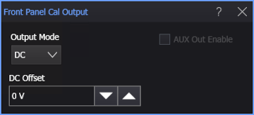
Output Mode — Select the signal that is output:
-
DC — This control outputs a DC voltage level on the Cal Out connector (but not the Aux Out connector).
This output is typically used by calibration and measurement standards labs such as NIST (National Institute of Standards and Technology) to measure the DC level against a known standard.
When DC is selected, there is a DC Offset field for specifying the DC voltage level.
-
Probe Comp, Probe Comp No DC — This setting puts a probe compensation square wave, with or without DC offset, into 50 Ω on the Cal Out connector. This waveform is typically used to adjust compensated passive probes. The square wave frequency is 750 Hz. The probe compensation levels depend on which option is selected (with or without DC offset).
When Probe Comp is selected, you can specify fast or slow Edge Speed. The edge speed applies only to Aux Out and not Cal Out.
-
Trigger Out — With this setting, your Infiniium oscilloscope sends a pulse to the enabled output when a trigger event occurs. The pulse is typically used to trigger other test equipment. This setting provides the lowest jitter possible (<100 ps jitter) on the Trigger Out signal. It is available only when High Bandwidth Trigger is enabled in the Trigger Conditioning dialog box.
-
Logic 0, Logic 1 — On Cal Out, these levels depend on the amount of DC voltage added. On Aux Out, the logic 0 level is about -400 mV and the logic 1 level is about -100 mV.
-
Pulse Positive, Pulse Positive Single, Pulse Negative, Pulse Negative Single — A repeated or single positive or negative pulse signal.
Enter the width of the pulse in the Pulse Width field.
When a single pulse is selected, click Send Pulse to output the single pulse.
-
Frequency Synth — A high-frequency signal synchronized with the oscilloscope timebase clock.
-
Timebase Clock — The 400 MHz signal used for the oscilloscope's timebase.
-
-
Aux Out Enable — Available in certain modes, this specifies whether the signal is output on the Aux Out connector as well as the Cal Out connector.